Often a need arise to add a current sensor in your project, when you’re making an electric energy meter or a master/slave control switch for instance. Picking out the right theme for monitoring current consumption in a project is very important toward its performance. Even though many choices exist for monitoring current, this month’s pick is the ACS712 current sensor module based on ACS712 fully Integrated, Hall Effect-based linear current sensor chip from Allegro (www.allegromicro.com).
The ACS712 5A Current Sensor Module
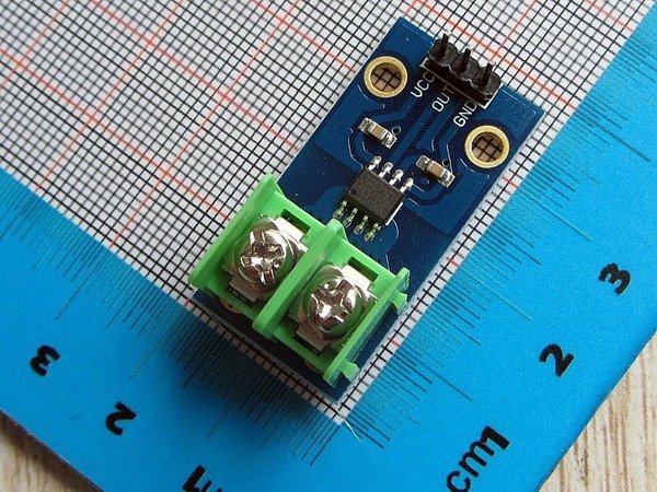
The ACS712 current sensor module introduced here can accurately measure current up to 5A. Recommended input supply voltage of the module is 5V dc, and its typical sensitivity is 185mV/A. Exact part number of the chip used in this 5A (ac/dc) module is ACS712ELC-05B. The ACS712 current sensor module outputs an analog signal that varies linearly with the unidirectional/bi-directional (dc/ac) primary sensed current within the measurement range specified. When no current is detected, then the output voltage will be Vcc/2. Obviously the output signal can be read via one analog I/O of a microcontroller like the Arduino.
Quick Test with Arduino
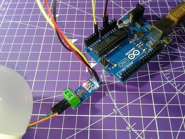
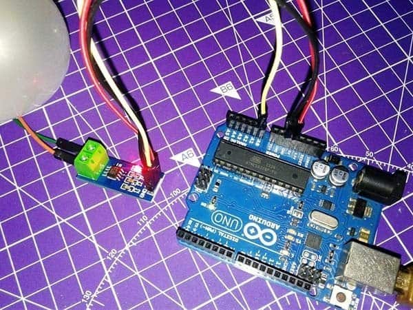
The first choice for quick test of the ACS712 current sensor module is undoubtedly an Arduino board because it’s a pretty easy experiment. Refer the following table for hardware connection details.
| ACS712 Module | Arduino Uno |
|---|---|
| VCC | 5V |
| OUT | A0 |
| GND | GND |
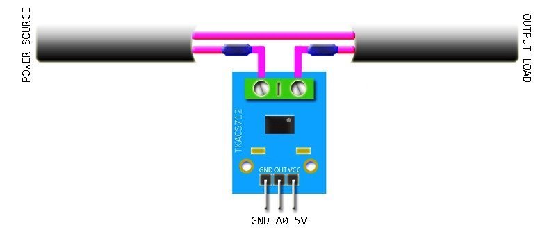
And then route only one wire from the power source to the output load through ACS712 module’s screw terminals. The figure below denotes the basic connection diagram of ACS712 module for current measurement. Take note, the hardware setup should not be used in areas close around substantial magnetic fields.
/*
 * Current Measurement Experiment
 * ACS712 Current Sensor Module & Arduino Uno
 * Based on a demo code by Elecrow
 * T.K.Hareendran/2019
 * www.Codrey.com
 */

void setup() {
Serial.begin(9600);
Serial.println("ACS712 Current Sensor---Quick Test!");
Serial.println();
}
void loop() {
float average = 0;
for(int i = 0; i < 1000; i++) {
average = average + (.0264 * analogRead(A0) -13.51); // Tailored for 5A sensor/module
delay(1);
}
Serial.print("Current Measured = ");
Serial.print(average/1000);
Serial.println("A");
}
This code will bring the measured current readout in Ampere through Serial Monitor. I made two different dc current measurements – first one with a small dc bulb and the next with a small dc motor.
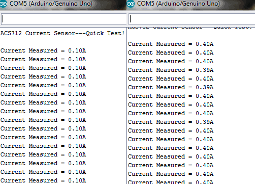
Frankly, ACS712 is not a good pick for precise current measurements but it will be useful in many situations where you only need to sense the presence of current, or to do a rough estimation.
Code & Maths
Typical sensitivity of the 5A current sensor is 185mV/A, and its nominal output voltage at 0A input will be Vcc/2 i.e. around 2500mV when Vcc is 5V. For a clear perception, just assume that the Vcc is 5V and the current measured is 3A. If so the module’s output will be 3x185mV + 2500mV = 555 + 2500 = 3055mV. This value, ‘seen’ by the analog channel as the ‘raw’ value, should be converted to mV, and the offset (2500mV) must be subtracted from it. Thereafter, dividing that value by the typical sensitivity value (185mV) will give you the measured current value. See how it’s done in the below example code.
const int analogIn = A0;
int mVperAmp = 185; // For 5A Version
int RawValue= 0;
int ACSoffset = 2500; // Assumed Vcc is 5.0V
double Voltage = 0;
double Amps = 0;

void setup(){
Serial.begin(9600);
}

void loop(){
RawValue = analogRead(analogIn); // Read A0
Voltage = (RawValue / 1024.0) * 5000; // Calc mV
Amps = ((Voltage - ACSoffset) / mVperAmp); // Consider Offset
Serial.print("Raw Value = " ); // Show the Calc mV
Serial.print(RawValue);
Serial.print("\t mV = "); // show the measured voltage
Serial.print(Voltage,3);
Serial.print("\t Amps = "); // show the measured current
Serial.println(Amps,3);
delay(3000); // Wait for 3000mS
}
If you want to play with the ACS712 Arduino Library, go to GitHub through this link https://github.com/rkoptev/ACS712-arduino. The library Includes DC and RMS AC current measuring, and supports ACS712-05B, ACS712-20A, ACS712-30A sensors/modules. Here’s another useful link https://platformio.org/lib/show/1601/ACS712%20Current%20Sensor.
Recap
ACS712 is a bi-directional hall-effect current sensor that can sense both positive and negative currents. If the module runs on 5V, its output is set to 1/2Vcc or approximately 2.5V to represent zero current flow. So a negative current flow will go from 2.5V down and a positive current will go from 2.5V up. Since the calculation transforms 2.5V offset as 0A, you will get negative values (ghost readings) at times even with a little noise. Further, low resolution of the Arduino ADC won’t allow you to take accurate measurements.
Hopefully another fun thing to do. Enjoy!