Inspired by a dazzling Chinese design, I started thinking about making my own bicolor LED waistband with a few components lying around my workbench. In this post, you can see the basic design concept of a Bicolor LED Waistband supported by an Arduino microcontroller.
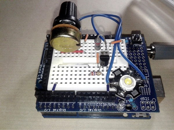
So, let us start with its simplest hardware setup diagram. Here it is:
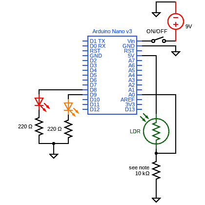
As you can see, the schematic is straight forward and self-explanatory.
The whole setup is powered by a 6F22 9V battery and the system is turned on/off by a small slide switch.
Two LED channels are provided here – one for red and the other for yellow.
A standard photoresistor (LDR) is also included to control the dual LED channels depending on the ambient light level.
As you might have guessed, this is an expandable concept, so it is easy to modify this basic design to suit individual needs and tastes.
For example:
You can use an Arduino Pro Mini, Lilypad, or a Digispark Attiny85 microcontroller board in place of the Arduino Nano board to make the model more compact and wearable.
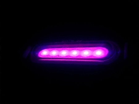
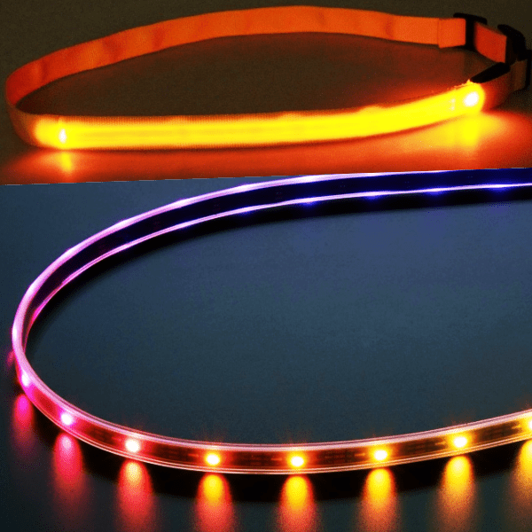
Single LED channels (red and yellow) can be modified to obtain more beautiful visual effects using flexible LED strips or similar electric lamps.
After replacing the 10KΩ fixed resistor with a suitable trimpot the ambient light level detection threshold can be set arbitrarily (it can also be tweaked via the provided code).
There are countless expansion possibilities in hardware and software for this design, right? Brainstorming can bring forth some marvelous ideas!
Then to the code part (Arduino Sketch):
void setup() {

  pinMode(A0, INPUT); //LDR INPUT A0
  pinMode(8, OUTPUT); //LED_RED D8
  pinMode(9, OUTPUT); //LED_YELLOW D9
}

void loop() {

  int ledOutput = (analogRead(A0)); //Read Light Level

  int ledO = map(ledOutput, 1, 1023, 0, 254); //Map

  if (ledO >= 128) {          //Threshold 1_YELLOW LED ON
    digitalWrite(8, LOW);
    digitalWrite(9, HIGH);
  }
  else                     //Threshold 2_RED LED ON
  {
    digitalWrite(8, HIGH);
    digitalWrite(9, LOW);
  }

  delay(49); //Halt

}
Not to mention the code is also canonic and easy to empathize!
If the code is explained a bit, the photoresistor outputs an analog voltage. Accordingly, with the command (analogRead(A0)); the system reads the value of the A0 pin to which the potential divider (photoresistor + regular resistor) is wired, and transfer it to a variable. If the light intensity value is below certain units, one light channel will turn on, while when the light intensity is above certain units, next light channel will turn on.
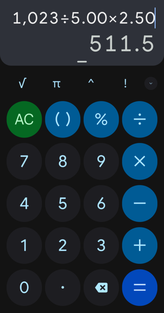
Assume at this point that the resistance of the photoresistor is 10KΩ at 10Lux. If so the analog terminal A0 will see a voltage around 2.5VDC at 5V system voltage.
The ADC reports a ratiometric value, means it assumes 5V is 1023 and anything below will be a ratio between 5V and 1023.
Since we use the 10-bit ADC of the Arduino on a 5V system, the ADC should report 1oLux as 512 (see below).
Jogging at dusk or dawn is not necessarily an option but often it is the only time you can squeeze a workout in. But note that such poor-light conditions obviously demand a distinct jogging gear for you. Since a glowing waistband can help motorists or other joggers see you, try making a unique gear yourself.
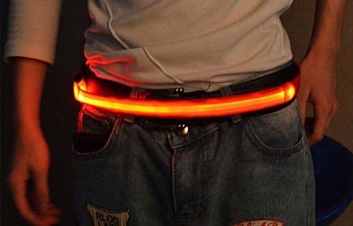
Well, let me jump to a quick conclusion to this post by sharing a few random pointers to help you make a nifty (and practical) glowing waistband.
Simple codes like the ones given here for Arduino can be easily ported to Attiny microcontrollers. So, a cute customized printed circuit board filled entirely with chip parts (SMDs) makes your build lighter and more affordable.
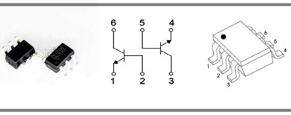
If so, a dual-NPN transistor, like the easily available MMDT3904/K6N, would be great here to drive several LEDs wired together in each channel (provided that the total current consumption must be less than 200mA per channel).
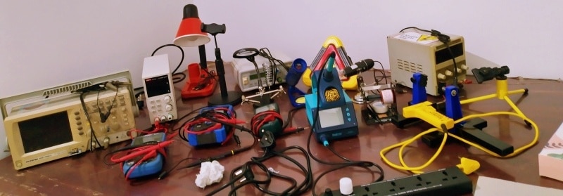
Tailpiece: At times, I have not included many photos of projects that have been tested on my workbench. Do not worry, almost all the projects posted here were tried and tested precisely as usual but not photographed. It is because I am moving to my new electronics lab stepwise and very tired from all that backbreaking work. The new venture (my dream project) is expected to be fully operational within a few months. Updates are on their way to you!