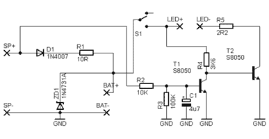
Self-lock delay switch is a simple timer module that produces a fixed square pulse.
It is designed around the 555 timer and uses a tricky negative edge trigger to ‘run and lock’ the timer. The circuit diagram of figure 1 shows this:
The module operates during initial power up and this turn off the LED to announce that the timing has started. At the end of the predefined period the LED illuminates and the timer’s output is reversed (from high to low). The timer delivers an output close to its supply rails and can sink/source about 200mA (maximum depends on supply voltage). The module also features a “fire” button to reset/restart the process by hand.
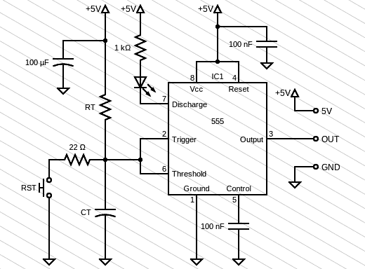
Although we normally think of the 555 IC as a timer/oscillator It can be used as an inverting buffer i.e. a NOT gate just like the arrangement as shown in the diagram below.
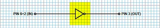
When the input voltage is between 1/3 and 2/3 Vcc the output remains in its present state. But when the input is Low (< 1/3 Vcc) it makes the output High, and when the input is High (> 2/3 Vcc) the output becomes Low.
Note that the input provides a high immunity to noise as once the output has switched (H/L) the input must change back by at least 1/3 Vcc to make the output turn back (a property called hysteresis).
Moreover, the buffer input has a very high impedance (~1MΩ) so it demands only a few uA or so of current, thus enables a high impedance signal source to switch a low impedance transducer.
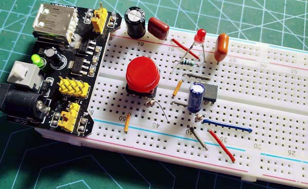
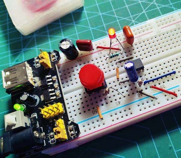
The point of this crude but effective self-lock delay switch is to control an external electric load (on or off) with a delay in operation. I tested my breadboard with a 100KΩ resistor as RT and a 100uF polarized capacitor as CT, and noticed a holdup close to 10 seconds.
From this, we know that when both TRIG and THRES of 555 timer IC are the same, OUT has a deterministic state, that means OUT is high (H) when TRIG=THRES=low (L), and OUT is low (L) when TRIG=THRES=high (H). Note at this point that in output Low state the voltage will be close to GND (0V). In output High state the voltage will be 1.7V lower than the supply voltage.
Taking the project idea a step further, the 555 timer IC is actually very well suited for driving a low current relay as its output can sink and source current enough to handle most small relays comfortably.
So, if you connect a 5V relay between the +5V rail and pin 3 of the 555 IC, it will energize only after around 10 seconds during initial power up but remains in that state thereafter. The contacts of that relay then can be used to switch electrical loads on or off with a predetermined delay.
The recommended relay for this design is the SONGLE SRD-05VDC-SL-C.
Although the push-pull output stage of the 555 IC automatically shunts the relay coil when the output is high, damping the back-EMF, it is probably still a right idea to fit a power diode (1N4007 or similar) across the relay coil.
Well, this project was certainly fun, and it helped me to safeguard some of my electrical appliances. I hope this writeup will convince you to build your own self-lock timer. Good luck, and have fun!