 This article is a mere pointer on how to build a mighty light-emitting diode flashgun controller. The presented project idea is intentionally kept do it yourself-friendly by using easily available components.
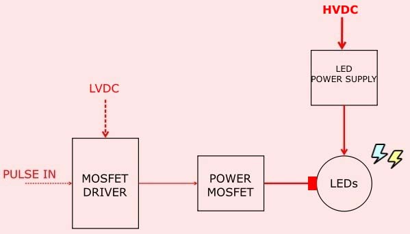
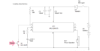
Before we step into the rest of the project story, it’s worthwhile to look at the simplistic system diagram/block diagram of my LED flashgun.
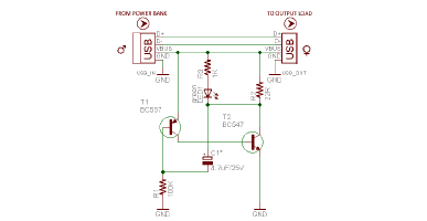
The basic idea of an LED flash gun appears fairly simple. Usually, in such a flashgun, high power LEDs are driven for very short periods using pulses of very short duration at much greater powers than they can tolerate when driven continuously. Below is the tried and tested schematic of my LED flashgun controller (v1). Let me say, this is in fact a slightly modified version of a belittled LED flashgun circuit once borrowed from the web.
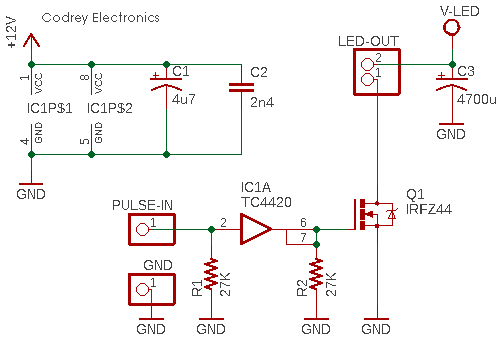
Yeah, it’s a few electronics inside here. I started with a TC4420 MOSFET gate driver (IC1A) and an IRFZ44 power MOSFET I had in the spare box.
- TC4420 https://ww1.microchip.com/downloads/en/DeviceDoc/21419D.pdf
- IRFZ44 https://www.vishay.com/docs/91291/91291.pdf
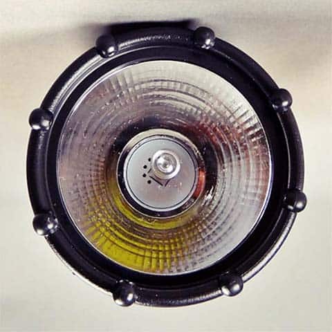
What is more, I ordered a kit of assorted ultra-high power warm and cool white LEDs more than two months ago from china, but it wasn’t delivered intime. So, I made a tricky flashgun from a 3W white LED headlight I had at home.
3W Hi-Power LEDs (quick reference) https://www.pcboard.ca/high-power-led-3-watt.html
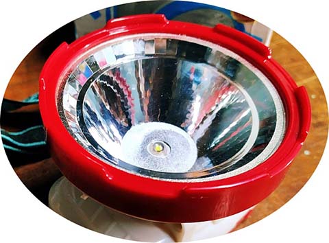
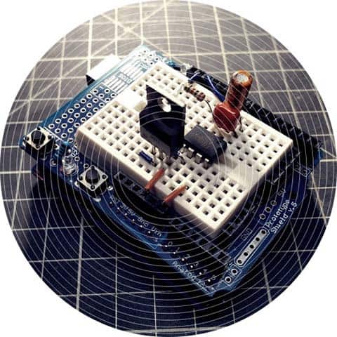
As you can see below, I rigged up the quick test circuit on an Arduino Uno Prototype Shield except the light head. Look, if you too are on a breadboard (probably not a good practice), then all parts must be kept physically close to each other in order to minimize impedance in the circuit.
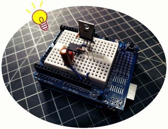
It’s very apparent that the IRFZ44 power MOSFET (Q1) works with the TC4420 gate driver and no ailments so far. I’m not sure the pull-down resistors (R1 & R2) are necessary or not but they’re still in situ. But I didn’t include a gate resistor or other supporting components. Perhaps I will extend this experiment by employing a few more components and post the results later. Likewise, the breadboard version worked but it was clear that a devoted PCB would be required to take things further. I will add to this post when I have taken things a bit further.
Anyway, I was able to get the quick breadboard version up and running successfully with TTL level narrow drive pulses and modest overdrive currents (it’s absolutely not the final test). See the following Arduino Uno code snippet used at that time.
/* Dirty Test Pulse Generator for LED Flashgun Controller */


int strobePulse = 13; // Pulse Output = D13
//int strobePulse = 2; // Pulse Output = 2

void setup() {

  pinMode(strobePulse, OUTPUT);
}

void loop() {

  digitalWrite(strobePulse, HIGH);
  delay(50);
  digitalWrite(strobePulse, LOW);
  delay(5000);
}
After a thorough search it’s found that the absolute maximum peak pulsed forward current of my test LED is 1500mA (100ms). And then I started to look into how far I could push the test LED in terms of the drive current. I was able to get to 3A without destructing the LED. I noticed that someone had been able to push 3W LEDs over 15A using higher frequencies and lower durations. But I couldn’t get proper components to conduct a daring test like that.
Note that common LEDs can also be ‘overdriven’ at higher intensities than the nominal values, thus making them brighter but only for a limited amount of time. In this case we say that the LED is operated in “strobed mode”. It’s often asked by hobbyists (delving into highspeed flashgun circuits for highspeed photography) whether it is safe to operate power LEDs with pulsed currents far above the maximum datasheet rating. Yes, but it depends!
Power LEDs are usually happy to work with currents that are several times higher than the maximum rated current. But the exact amplitude that a particular LED can withstand is also a function of the duration and frequency of the drive pulse. Beyond a certain threshold, the overcurrent drive will lead to an immediate catastrophic failure of the LED with two general failure modes – a short circuit or an open circuit. So, while experimenting, be aware of the physical limits that must not be exceeded in order to avoid electrical overstress, and trade-offs that may adversely affect efficiency, chromaticity, and long-term reliability.
As far as I’m aware, power LEDs can be strobed in less than 1 us, but cannot emit light of great intensity without fatally overheating (traditional xenon tube flashguns are still limited to flash durations of around 40 us only). This problem can to an extent be overcome by overdriving many LEDs at the same time preferably with a narrow drive pulse.
Well, with all in mind you can now rig up your own mighty LED flashgun along with an associated microcontroller that can be used for highspeed imaging/photography. Good luck with your project!
Credits & References
- https://www.opto-e.com
- CREE.COM/XLAMP
- https://www.electronoobs.com/eng_arduino_tut12.php
- https://www.doc-diy.net/photo/xe2020_highspeed_flash/
- https://www.instructables.com/High-Speed-Photography-1/
- https://petermobbs.wordpress.com/2015/02/25/brighter-faster-flashes-from-an-led-based-flash-gun-part-2/
Interesting. I’m planning something similar….
227 white LEDs on a board, running from 7,4v lithium with a 220ohm 50w resistor. Switching is planned to be powered by a microcontroller with flash times of less than 100 microseconds.
Zephod Beeblebrox: Thanks! Wishing you all the best with your project. Also, I hope we get some updates when it’s done 👍
I needed a short-duration (30 micro-seconds) LED flash. After some tests and a couple of failed LEDs, I settled on 3W LED that seemed to work fine on a small 12V battery, driving around 4A through it. The intensify was sufficient for my application. I used 555 timer to form the short pulse and noticed that high-speed MOSFET driver doesn’t do anything positive for me, as 555 can drive MOSFET just fine without a driver. I needed a small circuit, but smaller MOSFETS with higher Rdson didn’t work well, and larger one (IFR640N) worked great but was too big. I ended up removing a MOSFET from a dead PC motherboard (9030AL) and it worked super well. It also has a plenty of power (38A) to handle anything.
photogeek: Thanks for your comment!
I couldn’t see your schematic, but the 555 IC can drive a power MOSFET in most cases, which should be sufficient for LED driving applications. But often we need a dedicated gate driver in power electronics.
I’m glad you made your project a success. But driving a 3W LED with 4A @12V current confuses me. AFAIK such an LED typically requires only 700mA. If I misunderstood your explanation, let me know.