 The prime intention behind this little post is to share some notes about analog optocouplers which might be useful for hobbyists, students, etc. I know many novices who want to learn the secrets of analog optocouplers and digital isolators, but cannot afford to spend much money for their burning desires!
Well, let’s start with a simple question. Actually, what is an analog optocoupler?
What is an analog optocoupler?
You are all familiar with standard optocouplers. A standard optocoupler basically consists of a light transmitter and light receiver mounted inside a light-proof shell. The analog optocoupler (or analog insulator) comes from the same optoelectronics family but is slightly different in most physical and electrical terms.

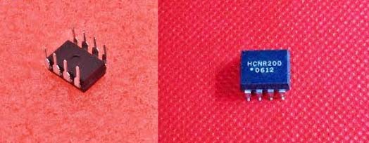
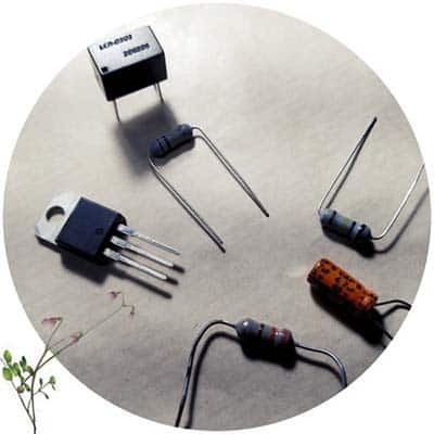
In the below figure, you can see a famous analog optocoupler – the HCNR200 from Avago Technologies. This high-linearity analog optocoupler consists of a high-performance AlGaAs LED that illuminates two closely matched photodiodes (https://docs.broadcom.com/doc/AV02-0886EN).
An analog optocoupler is an excellent solution for many analog signal isolation problems. It can be used to isolate analog signals in a wide variety of applications that require good stability, linearity, bandwidth, and low cost. By appropriate design of the application circuit, it can be of operated in many different modes, including unipolar/bipolar, ac/dc, and inverting/non-inverting.
Talked enough, now let’s do something practical with an analog optocoupler. Before that, take a trip through this page https://www.electroschematics.com/vactrol-a-lazy-walk/
How to play with an analog optocoupler?
Analog optocouplers are still widely used in audio circuits, motor drivers, power monitors, etc. The analog optocoupler is commonly added to isolate the analog signal in the front end of an application circuitry, i.e., it will be placed between two segments of the application circuitry to provide perfect galvanic isolation (https://en.wikipedia.org/wiki/Galvanic_isolation) of the analog input and output signals.

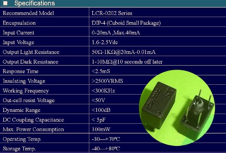
What I introduced above is a costly (but feature-rich) HCNR-200 analog optocoupler. So, for the simple practical experiments, I pick a cheap and easily available analog version LCR-0202. Since the LCR-0202 analog optocoupler consists of a light-emitting diode (LED) and a photoresistor (LDR/CdS Cell) to provide linear analog optical coupling, we can change the output resistance by feeding a variable current at the input. Below you can find its quick specifications. By the way, note that Cadmium sulphide (CdS) photodetectors (also known as photoresistors or light-dependent resistors) are high resistance semiconductors that operate as light-controlled variable resistors.
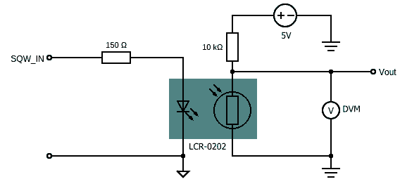
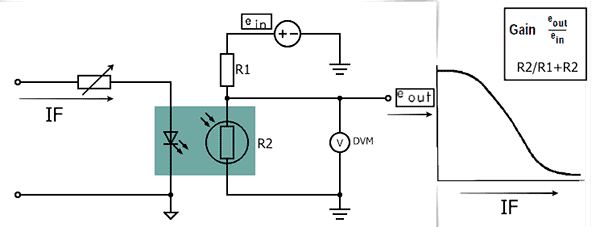
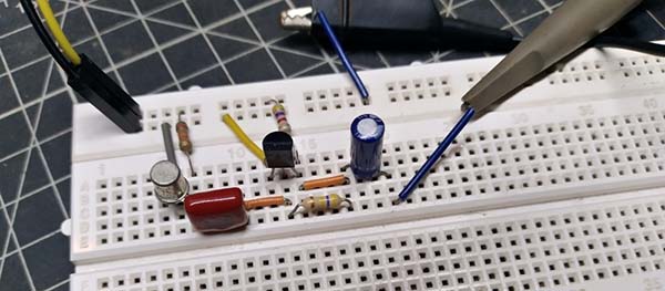
So, now we’ve the LCR-0202 analog optocoupler that has an optically-coupled LED and LDR inside. In order to test its basic functionality and/or to compare different LCR-0202 devices, we can use the crude test setup shown below. The idea is to apply a low-frequency square wave pulse (steady or variable) at its input and measure the dc voltage rendered by the potential divider wired at the output. Simple, yeh?
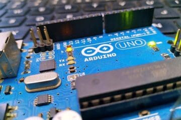
No doubt, the most popular Arduino sketch is BLINK which you will find on most Arduinos when shipped. As generating a square wave is essential here, you can use the same Hello World BLINK sketch to proceed with your quick functionality test. The default BLINK code will generate a low-frequency square wave signal of 0.5Hz with a ½ duty cycle. Needless to say, you may improve the square wave output over a wide range by modifying the parameters of the delay function.
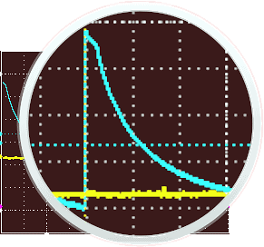
With this quick and easy setup, you can test the rise/fall times of an analog optocoupler as well, perhaps better with a short input pulse so that the optocoupler is triggered with a sharp pulse, and then left to fall.
Nevertheless, I couldn’t precisely measure the fall time of LCR-0202 so far but it seems to have a comparatively slow and clean fall time presumably good for audio electronics (see below). I will share more about my revised test setup & process in a subsequent post.
Quick sum-up
Okay, now we know that a common analog optocoupler also called an analog optical isolator(AOI), consists of a light-tight package which houses a light source and one photoconductive cell. Through control of the input current (or voltage) applied to it, the output resistance can be varied. The output resistance can be made to switch between an on/off state or made to track the input signal in an analog manner. Analog optocouplers have been found to provide a very economic and technically superior solution for many applications because a small change in input signal can cause a large change in output resistance. The fast turn-on and slow turn-off characteristics can be used to advantage in many practical applications. Here is a list of only a few examples where analog optocouplers have been used:
- DC isolators
- Feedback elements in AGC circuits
- Audio signal limiting and compression
- Noiseless switching
- Logic interfacing
- Noiseless electronic potentiometers
What is a digital isolator/magnetic isolator?
Analog isolation amplifiers find many applications where high isolation is required, such as in medical instrumentation. Digital isolation techniques provide similar galvanic isolation and are a reliable method of transmitting digital signals without ground noise. The availability of low cost digital isolators solves most system isolation problems in data acquisition systems.
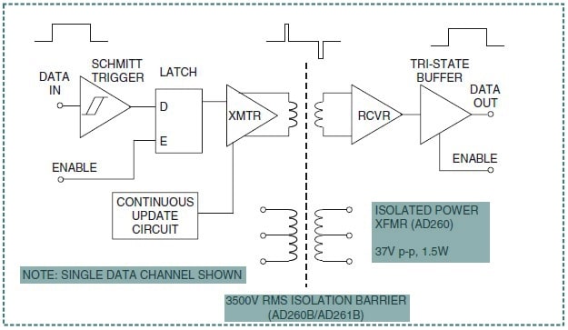
A Digital Isolator operates on the principle of transformer-coupled isolation (magnetic isolation). For example, the AD260/AD261 family of digital isolators (operates on the principle of transformer-coupled isolation) provide isolation for five digital control signals to/from high speed DSPs, microcontrollers, or microprocessors. The AD260 also has a 1.5 W transformer for a 3.5 kV rms isolated external dc/dc power supply circuit (https://datasheet.octopart.com/AD202JN-Analog-Devices-datasheet-2342.pdf).
A simplified schematic of one channel of the AD260/AD261 is shown below. As you can see, the data input is passed through a Schmitt trigger circuit, through a latch, and a special transmitter circuit which differentiates the edges of the digital input signal and drives the primary winding of a proprietary transformer with a set-high/set-low signal. The secondary of the isolation transformer drives a receiver with the same set-hi/set-low data, which regenerates the original logic waveform.
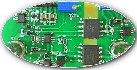
This is the photograph of a quite popular CJMUC-1201 magnetic isolator breakout board/module:
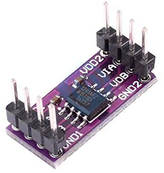
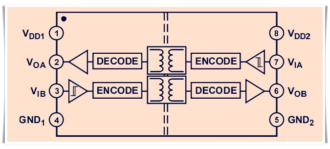
This compact module is based on the ADuM1201 dual-channel digital isolator from Analog Devices (https://www.analog.com/media/en/technical-documentation/data-sheets/ADuM1200_1201.pdf). See its functional block diagram below.
Well, with a few projects based on analog optocouplers in progress, I would like to take a short break now. I will share those projects in a few weeks. In the meantime, let yourself examine what you have learned so far.
What have we learned so far?
Revision has its own reward, so I’ve summarized this for you!
- There are many kinds of optocouplers/optical isolators, but the most common is the
- LED/phototransistor type.
- A basic analog optocoupler usually has a photoresistor/photocell at its output.
- Since the output element is a resistor, the voltage applied to the output resistor maybe DC and/or AC and the magnitude may be as low as zero or as high as the maximum voltage rating.
- Transformer-based (magnetically coupled) isolators can replace optocouplers. Such digital isolators send digital signals across potential differences of hundreds or thousands of volts. Magnetic signal coupling is faster and uses less power.
The two-terminal variable resistor at the output of an analog optocoupler may be used in a voltage divider circuit as shown in the below figure:
Next in this series »
Next is the little do it yourself project based on the LCR-0202 analog optocoupler. Continue to see the project “Arduino Garden Lights Controller”!
Credits & References
- Google Images, Wikipedia, eBay & Amazon
- Aolittel Technology Co., Ltd
- Analog Devices
- Agilent Technologies
- Avago Technologies
- Silicon Labs
- EDN (https://www.edn.com/)
How to interface the same with 230V , 50Hz AC for measuring AC voltage with Arduino ?
How to select resistor values ?
Ronie: Note that you can use optocouplers for AC voltage detection, but not so easily for AC voltage level measurement. I have no design with HCNR200 for such a task so far, but it seems practical.
If you are still concerned, I recommend you to read this at first to get the gist of it https://www.re-innovation.co.uk/docs/voltage-measurement/
See also my earlier writeup about ZMPT101B AC Voltage Sensor Module
https://www.electroschematics.com/voltage-sensor/
Hope this helps. Best regards, TK.