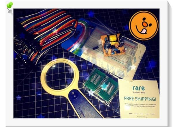
It was during Christmas week last year that I received an unexpected gift packet from an online store in India. What caught my immediate attention in that collection was the very small microcontroller chip CH551G. Of course, the CH551-x series MCUs are rich with features that are rarely known (at least in my case). So, first of all, thanks to Rare Components (https://rarecomponents.com) for helping me start my next experiment with some new design ideas. And, of course, for the priceless gift!
This is the link to get the product right at your doorstep (no affiliation) https://rarecomponents.com/store/ch551g?search=CH551
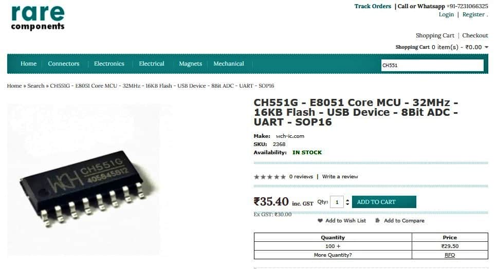
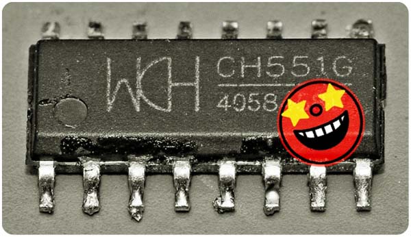
The CH551G is a low cost 8051 core MCU that comes in a SOP16 package with tons of attractive features. The SOP16 package makes it interesting for small-scale hand-soldered projects where other cheap microcontrollers are difficult to use because of much smaller packages which are not easy to solder by hand. Below you can see a quick overview. It’s hard to resist trying one!
- 8051 Core
- 24MHz Clock
- 10KB ROM
- 768B RAM
- 128B FLASH
- 0 Slave with up to 12MBit / s
- 2x PWM Channels
- 4x Capacitive Touch Channel
- 1x HS UART
- 1x SPI M/S
- 2x EXTINT
- 3x Timers
Getting started with the WCH CH551G
When I first read about the 551G microcontroller, I thought it would be interesting to try out someday. Key part of the attraction is the embedded USB transceiver. Moreover, it’s based on the 8051 which is a widely used and well-documented architecture.
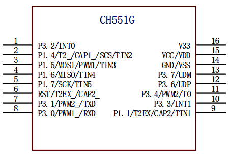
So, remember, CH551G is an enhanced e8051 core single-chip microcomputer compatible with MCS51 instruction set. 79% of its instructions are single-byte single-cycle instructions, and the average instruction speed is 8-15 times faster than the standard MCS51. The following is the pinout diagram of CH551G (for reference purposes only).
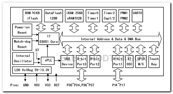
Also, see this internal block diagram, I copied from scant English documentation:
Now it’s worthy to note that the Chinese company WCH sells an extremely affordable 8-bit microcontroller family under the series CH55x, which is based on the architecture of the 8051 and has a USB interface. The low-cost microcontrollers in this series include WCH CH551, CH552, CH554, and CH559. The CH551 and CH552 share the same die – probably some features of the CH551 are simply deactivated. For example, the ADC is disabled in CH551G.
To the best of my knowledge so far, the CH55x series MCUs come with a bootloader that allows to use both the USB or the serial interface (the bootloader eats 2KB of the flash space, and cannot be overwritten using the USB or serial interface).
This is the link to download CH551G Datasheet (Chinese) https://pdf1.alldatasheet.com/datasheet-pdf/view/1147067/WCH/CH551G.html
Since I have never used CH551G microcontroller yet, this seemed like a good opportunity to learn more about it. So, I picked one of them from my gift packet and made a crude experimental hardware setup on the common breadboard with the help of an “SOP to DIP” PCB adapter (just to start my first attempt). I also used a “Micro USB Breakout Board” already included in the gift packet.
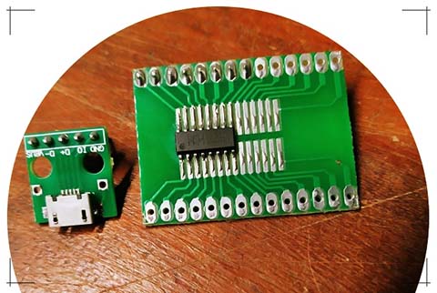
This is how I wired my quick hardware setup on the breadboard.
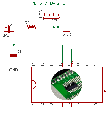
Below you can see a much simpler and easily perceivable image of the USB interface.
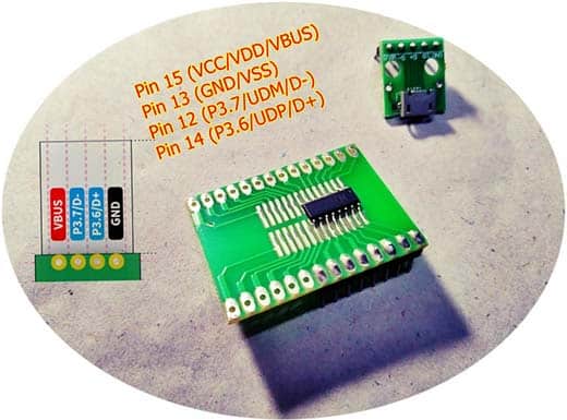
Although not shown in the previous schematic, the power input terminal (Pin 15) needs to be connected with a 100nF power decoupling capacitor. Pin 15 (VBUS/VCC/VDD) is the power input (3.3V to 5V, 2.8V minimum), whereas Pin 16 (V33) is the low-current 3.3V output coming from the LDO regulator which resides inside CH551G. The purpose of the 2-pin jumper JP1 will be explained later.
Needless to say, instead of buying a readymade CH551G module, I simply picked a bare CH551G chip and soldered it on a breakout board. I did it with the intention of eventually trying to build a CH551G quick development board myself (I’ll be giving it a shot soon). Close in time is the quick test of my CH551G breadboard setup. Okay, let’s get off the ground!
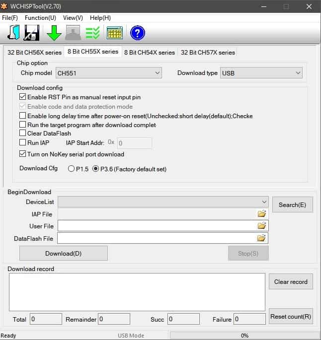
For the first test, in addition to the breadboard setup, I’ve used WCHISPTool (V2.70) on Windows 10. The tool can be found here http://www.wch.cn/download/WCHISPTool_Setup_exe.html
Sadly, one thing not clearly explained in the web documentations of CH551G is the Windows driver installation tips and tricks. I had learned (and verified) that it can be done in Windows 7 by using “Zadig” to set up the right driver. Zadig (https://zadig.akeo.ie/) is a Windows application that installs generic USB drivers, such as WinUSB, libusb-win32/libusb0.sys or libusbK, to help you access USB devices. Here you can find a related article authored by me a couple of years https://www.electronicproducts.com/hands-on-review-analyze-signals-with-free-open-source-sigrok-pulseview/
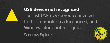
However, due to the Windows 10 (x64) driver setup problem I made repeated attempts but failed miserably!
Surely there is a ray of hope ahead. So, I will continue this story through the upcoming part of this post. “There is no failure except in no longer trying!”
In the meantime, you can go through some useful CH55x MCU resources similar to those listed below: