This is a quick primer on analog signal processing, which lets you smooth out the noise from analog readings in Arduino microcontrollers, resolving one of the major disquiets of analog sensor inputs, very easily.
Recently, while experimenting with an analog moisture sensor I noticed that it makes roughly pretty inconsistent numbers on each measurement. While introducing a little delay can normalize things a bit, I cherished to make the discrete analog sensor data as clean as possible. Therefore I did a lengthy Googling, and in the end, I acquired plenty of data right to assist me in getting going with my primitive thoughts.
In principle, noise in electronics is the undesired signals that step in with the real signal that is to be transmitted electronically. There’re so many noise types in electronics circuits caused by several different effects. In this particular primer, we’ll look into simple ideas viable for polishing noise in Arduino’s analog sensor tracks efficaciously. I know this is not a new topic but others, like myself, may find it as exceedingly useful as it is still relevant.
Arduino & Analog Input
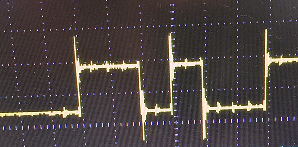
While using an analog sensor (light, sound, impact, temperature, etc) with an Arduino it’s quite usual that the analog sensor input often has troubling noise or jitter in the data it renders.
The ATmega controllers used in the Arduino contain an onboard six channel (eight channels on the nano and mini) analog-to-digital (A/D) converter. The converter has 10-bit resolution, returning integers from 0 to 1023. Even though the main function of the analog pins is to read analog sensors, the analog pins also have all the functionality of GPIO pins (still with internal pull-up resistors). In order to see more details (few caveats, as well) of the Arduino analog input pins, you may go to https://www.arduino.cc/en/Tutorial/AnalogInputPins
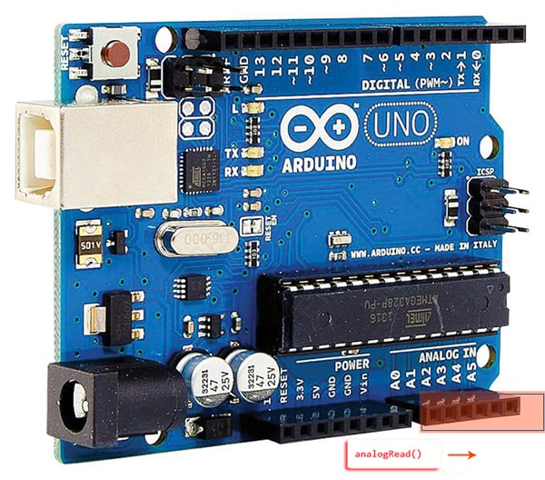
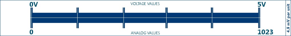
The analogRead() function reads the value of an analog input pin, reads an integer between 0 and 1023, while the analogWrite() function simply writes a value to an output pin with pulse width modulation (PWM), writes an integer between 0 and 255 which leads in a voltage value between 0 and 5V. Recall that analog means you can have a value other than 0 or 1. The analogRead() function reads a value from an analog input pin that can range between 0 and 1023, as you just caught out (look at the ruler).
To put it simply, each analog input pin of the Arduino is a 10-bit analog-to-digital converter (ADC), which means there’re only 1024 discrete voltage levels (2^10) the ADC can register. When we read an analog pin, the integer that comes back is a discrete level, a number between 0 and 1023. According to ATmega328P (the brain of Arduino) official datasheet, the analog input impedance is claimed to be 100MΩ, however during an actual sample, the input resistance is temporarily much lower as the sampling capacitor is charged up. So, it’s advised that whatever you link up to the analog input have an output impedance of 10KΩ (or less) for better accuracy. And, the ADC clock for a 16 MHz Arduino is set to 16 MHz/128 = 125 KHz. Each conversion in AVR takes 13 ADC clocks so there’s 9615 samples per second (125 KHz /13 = 9615 Hz). That is the maximum possible sampling rate, but the actual sampling rate in your application depends on the interval between successive conversions calls.
As a side note, the Arduino Uno board is the first in a nifty series of USB Arduino boards, and the reference model for the Arduino platform. “Uno” means one in Italian and was chosen to mark the release of Arduino Software 1.0. The Arduino Uno board and version 1.0 of Arduino Software (IDE) were the reference versions of Arduino, later evolved to newer editions. Thanks to https://engineering.eckovation.com/arduino-architecture-explained/ for this info!
Better Analog Read with Arduino
Let’s bring back our main theme and take a look again. To get resumed, now I will explain what is actually going on in a real world Arduino analog sensor experiment. The little example is useful for smoothing out the noisy readings from wandering analog sensors. Perhaps this analog signal smoothening trick can be improved in hardware, but often it’s easier to do in software. I wrote my own code to do this, but later found an even better one suits you in the web.
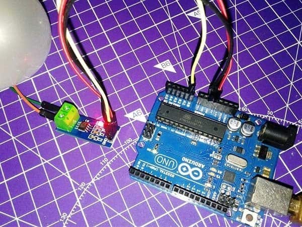
This experiment uses the “ResponsiveAnalogRead ArduinoLibrary” with an Arduino Uno board to read from an analog sensor and smoothen the raw data with the library functions, in order to have a noise-free reading. You can use this link to download the requisite Arduino library https://github.com/dxinteractive/ResponsiveAnalogRead
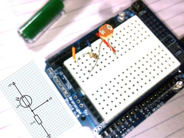
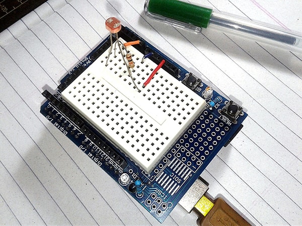
Hardware setup (LDR+10K Resistor) for the analog sensor smoothing experiment is shown below.
This is the code (Arduino Sketch) for the analog sensor smoothing experiment:
#include <ResponsiveAnalogRead.h>
const int SENSOR_PIN = A0;
ResponsiveAnalogRead analog(SENSOR_PIN, true);
void setup() {
  Serial.begin(9600);
}
void loop() {
  analog.update();
  Serial.print(analog.getRawValue());
  Serial.print("\t");
  Serial.print(analog.getValue());
  if (analog.hasChanged()) {
    Serial.print("\tchanged");
  }
  Serial.println("");
  delay(20);
}
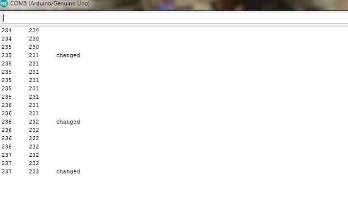
Almost there, you should see the sensor readings (in response to different light levels) – first one denotes the raw data and the second one denotes the smoothed data. In case you don’t have an LDR handy, you can use a 10K potentiometer there with its first pin to 5V, last pin to GND, and the middle pin (wiper) to A0. The final output seems alike this (see below image) in your Serial Monitor, provided the baud rate setting is aright.
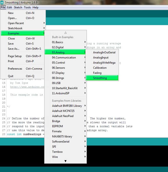
Remember that Arduino also comes with an analog smooth code example sketch, so check both out that too to see which one suits you.
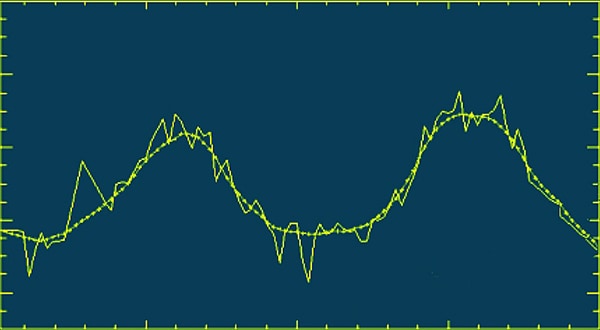
Besides, visual learners can cheerfully observe the effects by using the Serial Plotter to graph data both before and after the analog signal smoothing. See a related primer prepared by me a while back https://www.electroschematics.com/visualizing-data-arduino/.
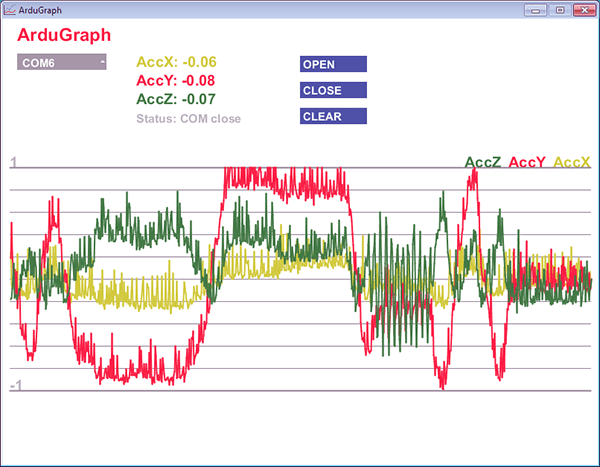
Also go through this link to meet ArduGraph (look above), which is a nifty open-source serial graph monitor for Arduino https://www.open-electronics.org/guest_projects/ardugraph/
Getting through
Finally, in this primer, I’ve shared some key points on how to smooth Arduino’s analog signal readings. I believe that you enjoyed this little post and the information that I’ve given. Have fun and let me know in the comments if you build something nice with a clever analog signal smoothing setup. Thank you for reading!