I was looking around for a little garden electronics project, and I came up with the idea of making a strikingly different Arduino garden lights controller. The reason I picked such a theme is that it gives me the chance of playing with some interesting ideas and some adaptable code.

At first, we need to build an AC230V lamp control/driver interface for this project. Don’t worry, this part is pretty much the most trivial circuit imaginable. In fact, all we have to do is to connect the incandescent garden lamps we want to drive to one of the digital output pins I/Os of the Arduino, but through this driver circuit which provides a clean galvanic-isolation (https://training.ti.com/ti-precision-labs-isolation-what-galvanic-isolation). Okay, let’s see exactly what the control interface looks like, by studying the below schematic.
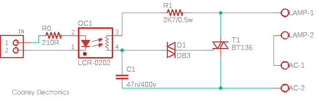
The forepart of this design is an analog optocoupler LCR-0202 (OC1). This particular optocoupler is a combination of a light-emitting diode (LED) and a photoresistor (LDR) both enclosed inside a compact lightproof shell. Actually, this component is a Vactrol (https://sdiy.info/wiki/Vactrol). See, Vactrol is a great way to add voltage control to what would otherwise be a variable resistor in a circuit.
Related Datasheets:
- LCR-0202 http://pliki.aksotronik.pl/lcr0202.pdf
- DB3 https://www.st.com/resource/en/datasheet/db3.pdf
- BT136 https://www.mouser.com/datasheet/2/302/BT136-600E-352978.pdf
Warning: AC230V powered project. Careless handling of dangerous high voltage can result in severe personal injury or death!
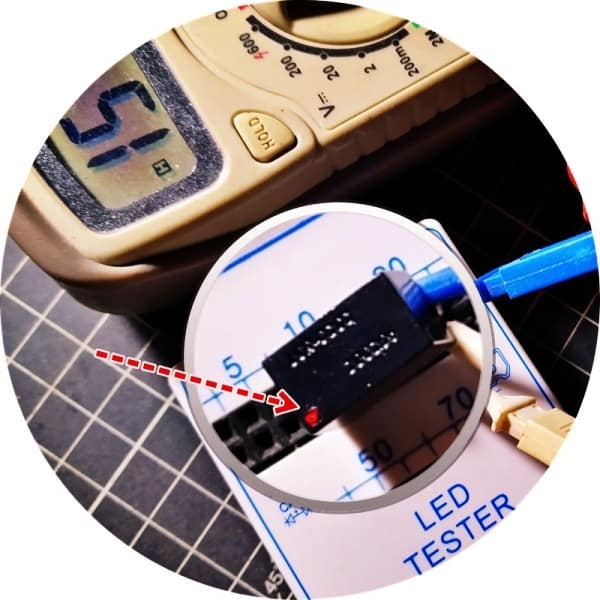
I tested my Vactrol (LCR-0202) with the help of an inexpensive Chinese LED tester, and it’s observed that the Vactrol has an output dark resistance in MΩ range (>10MΩ).
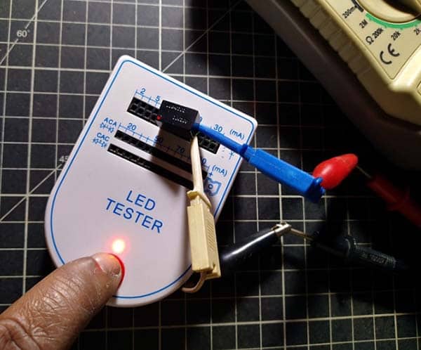
Subsequently, an output light resistance about 120Ω was registered when triggered with 10mA input current (IF). And, it’s about 150Ω when IF = 5mA. The voltage drop observed across the input (VF) was around 2V. Cool stuff – it has an on/off status notification dot too!
Next crucial part of the design is a common 4Q triac – the BT136 (T1). Triac is the most commonly used device for switching and power control of ac systems as it can be switched on by either a positive or negative gate pulse, regardless of the polarity of the ac supply at that time. This makes it ideal for controlling an ac lamp or motor load with a very basic circuit setup. Here in this design, triggering voltage for the triac is derived from the R1-LDR-C1 combination thru the final key part – the DB3 diac (D1). Note that in most ac switching applications, the triac gate terminal is associated with the MT1 terminal, similar to the base-emitter relationship of a BJT.
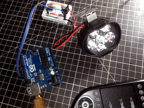
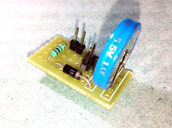
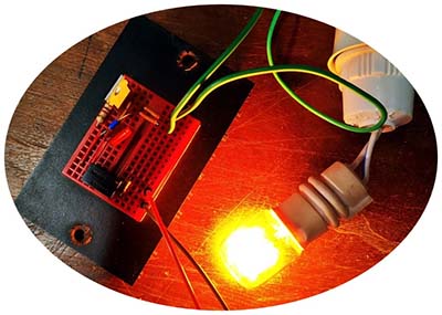
This crude circuit, which is a near-replica of the traditional ‘textbook’ triac lamp dimmer circuit, is passable for the proposed application. As usual, I made the quick test setup on a mini breadboard and tested it with an AC230V incandescent lamp. The input to the LCR-0202 Vactrol at that time was a simple 3VDC supply provided by one CR2032 coin cell.
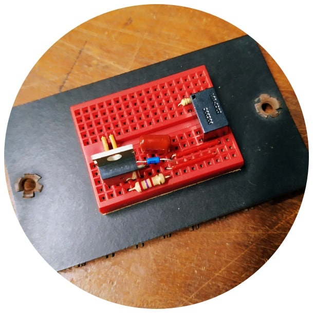
Thus, I successfully verified the basic functionality (on/off) of my AC230V lamp control/driver interface. Yup, it worked as anticipated!
If you too are up to this spot despite setbacks, great, now you can feed an appropriate input signal to your controller/driver setup from an Arduino or any other 5V/3.3V microcontroller. I leave it to you. Recall, then you’re going to play with fatal electricity – as always, safety first!
Anyway, below you can see a pretty simple Arduino Sketch to test your prototype. You must connect the D13 and GND headers of your Arduino board to the input socket (IN) of your prototype with the correct polarity. Later, you can spend some time modifying the value of R1 (and/or C1) to make your hardware build better.
void setup() {
  pinMode(LED_BUILTIN, OUTPUT);
}

void loop() {
  digitalWrite(LED_BUILTIN, !digitalRead(LED_BUILTIN));
  delay(250);
}
In this code, digitalRead() returns the current output value of the D13 pin: 1 if the pin is logic-high and the LED is on, 0 otherwise. We use the! (not) operator to invert that value, and thus toggle the state of the D13 LED and the LED inside the Vactrol. That’s all!
Why a Vactrol? Now to the natural question someone might ask – why did I choose a Vactrol for this project rather than using a common opto-triac/phototriac (https://www.vishay.com/docs/84780/appnote34.pdf)? Simple, I wanted you to get acquainted with Vactors as it will be useful for some ludicrously odd projects (the concept may already be familiar to you – if you’ve built audio-light modulator or similar circuits earlier).
Apparently, you can make a Vactrol yourself by getting an LED, pointing it at an LDR, and engulfing it in an opaque heat shrink tube so no external light can get in. However, you wouldn’t use a Vactrol for everything as its response is very non-linear, differ from another one, and a bit slow to act.
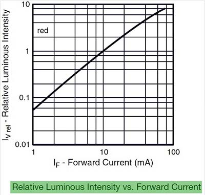
Now it’s also worthy to take note that the LED in a Vactrol follows all the same rules as a common light-emitting diode. LEDs have a minimum voltage before they turn on – usually, anything less than about 1.6V makes zero light, and beyond that LEDs brighten up rapidly with additional voltage and then get only marginally brighter with added voltage. So, it’s far better to control the LED brightness using variations in current, not voltage (look below).
I’m still in my kitchen, cooking the next part of this garden light circuit. So, stay tuned to get those tidbits! Meanwhile, if you find a bug, you can think of an improvement, or just want to make a comment, I will appreciate it. Thank you