For a while now, I’ve had need of a simple digital to analog converter circuit to be able to work with an Arduino microcontroller. To this end, I had a good search around and eventually found a useful piece of electronics – the MCP4725 I2C DAC module!
In this small article I will present a quick and dirty idea to play with the MCP4725 DAC module. The idea introduced here is a generic one that can be used with any Arduino edition. Anyway, I’ve experimented with an Arduino Uno as it’s only handy at that time. The Arduino firmware is quite short in length and I believe an easy one to follow.
Digital to Analog Conversion (DAC) is a difficult subject to bring up. However, before we go any further, let me shed little light on the theory part.
First off, note that an analog signal, by definition, is a nominally continuous electrical signal. The analog signal path implies a continuous signal in contrast to a digital signal path, which breaks everything into numbers. This is the main difference between analog and digital signal. A Digital to Analog Converter (DAC) is something that most of us take for granted. There’s one in your computer, one in your smartphone, and one in your satellite television box.
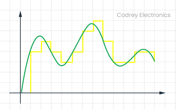
Since most real-world signals are analog, analog to digital (ADC), and digital to analog (DAC) converters are necessary to allow digital electronics to handle the analog signals. The function of a DAC is to convert a sequence of digital bits into an analog signal. That means, a DAC takes a binary number and converts it an analog voltage that is proportional to the binary number. If we feed a DAC with different binary numbers in quick succession a complete analog waveform is created. Simply note that there are two main types of digital to analog converters – the Binary-Weighted DAC and the R/2R Ladder DAC.
Frankly, building a DAC from scratch isn’t worth it. You’re better off buying a dedicated DAC IC or using the one built into your microcontroller or ecosystem module. So, let’s delve into the principal theme of this article. In case you still don’t quite understand or need much better information, the link below can help.
https://www.allaboutcircuits.com/textbook/digital/chpt-13/digital-analog-conversion/
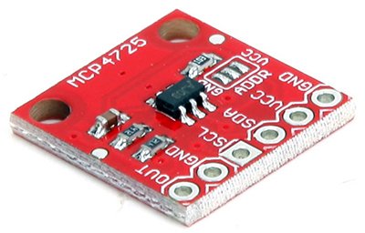
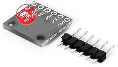
MCP4725 I2C DAC Module
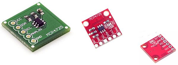
The DAC module introduced here is based on MCP4725. According to Microchip’s datasheet, the MCP4725 is a low-power, high accuracy, single-channel, 12-bit buffered voltage output DAC with a non-volatile memory (EEPROM). Its on-board precision output amplifier allows it to achieve rail-to-rail analog output swing. The DAC input and configuration data can be programmed to the non-volatile memory by the user using I2C interface command. The non-volatile memory feature enables the DAC device to hold the DAC input code during power-off time, and the DAC output is available immediately after power-up. The device also includes a Power-On-Reset (POR) circuit to ensure reliable power-up and an on-board charge pump for the EEPROM programming voltage. The DAC reference is driven from VDD directly. In power-down mode, the output amplifier can be configured to present a low, medium, or high resistance output load. The device has a two-wire I2C compatible serial interface for standard (100 kHz), fast (400 kHz), or high speed (3.4 MHz) mode.
This is the specification chart of the generic MCP4725 module brought out by China.
- 12-bit resolution
- EEPROM memory
- Power down mode
- Voltage: 2.7 V to 5.5 V
- Transmission speed up to 3.4 Mbps
- Default I2C address 0x60
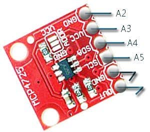
The nifty module draws less than 0.4 mA from the power supply with zero load at the output, and will deliver around 25mA to the load. It can accept up to 4096 possible inputs (12 bit DAC) to provide the analog output. Here, an output value of 0 is zero and an output value of 4095 is full scale, where the full scale value is determined actually by the reference voltage supplied to VCC pin. In this light, it’s important to take note that the power supply at the VDD pin should be clean as possible for good DAC performance.
You can ofcourse interface this MCP4725 module with Arduino to get a ‘true’ analog output. It’s extremely simple but note that Arduino does not support the Fast I2C (3.4Mbps) mode. Well, lets jump in…
We’re going to use the MCP4725 module to generate an exquisite waveform. There’s certainly many more experiments to do with the proposed setup (see above), anyway, the program for a quick tryout would look something like the one given below. The sketch example forked out here uses the quite popular Adafruit_MCP4725 library. So, at first download and install the requisite Adafruit_MCP4725 Arduino library https://github.com/adafruit/Adafruit_MCP4725
In the recent Arduino IDEs (1.6.5+) you can easily import requisite libraries using Library Manager. If you’ve no idea about adding or installing libraries, I propose reading this article https://www.arduino.cc/en/Guide/Libraries
#include <Wire.h>
#include <Adafruit_MCP4725.h>
Adafruit_MCP4725 dac;

void setup() {

pinMode(A2, OUTPUT);
pinMode(A3, OUTPUT);

digitalWrite(A2, LOW);
digitalWrite(A3, HIGH);

Serial.begin(9600);

dac.begin(0x60);
}

void loop(){

  for(int x=1; x<4096; x++){
    dac.setVoltage(x,false);
    delayMicroseconds(1);
  }
  for(int x=4095; x>1; x--){
    dac.setVoltage(x, false);
    delayMicroseconds(1);
  }
}
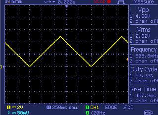
This is a random output waveform capture of the code:
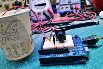
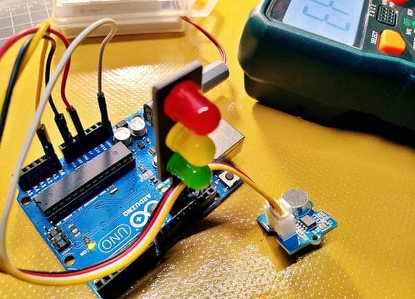
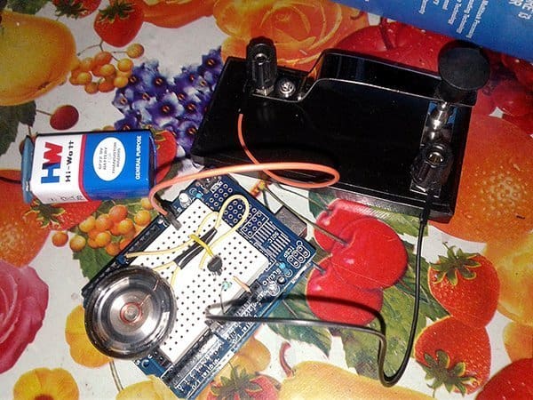
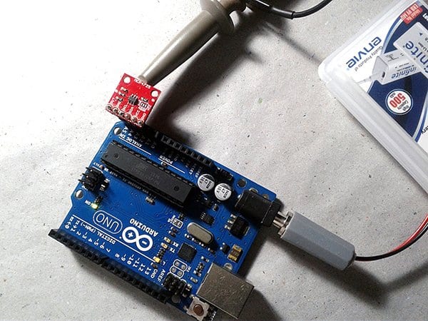
And, a couplet of quick lab snaps:
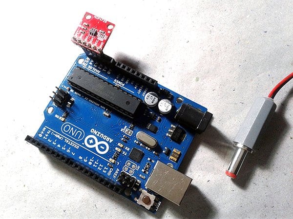
It’s worthy to notice that the I2C interface pull-ups in the module are enabled by default. So, if you’re going to have more than one module on a bus, you’ll also want to disable the pull-up resistors on all but one module by removing the traces on the jumper pad located at the back of module.
In my view, the MCP4725 I2C DAC module is a wonderful little piece of precise hardware where design simplicity and little footprint is sought after, and for projects called for the settings to be stored during the power-off time. Okay, now you should be able to get your MCP4725 I2C DAC module working the way you’d like and integrated it into your next project. And that’s all folks!
Postscript: Two years ago I unveiled one thought looked alike. You can find that on the post available through this link https://www.electroschematics.com/arduino-dac-guide/