When you want beautifully smoother color transitions, a better way to do it is to try HSL or HSV rather than just driving LEDs via RGB colors. So, this little post is about controlling RGB LEDs that way. Chances are, you may never exploit all 16 million colors available to you with your RGB LEDs. But it seems simple, let’s see how!

Wikipedia says,
HSL (hue, saturation, lightness) and HSV (hue, saturation, value), also known as HSB (hue, saturation, brightness) are alternative representations of the RGB color model, designed in the 1970s by computer graphics researchers to more closely align with the way human vision perceives color-making attributes (https://en.wikipedia.org/wiki/HSL_and_HSV).
Let me give you a few hints to help you start exploring and implementing two different RGB crossfade approaches.
Actually, there’re many fun ways you could crossfade an RGB LED depending on which colors you want to illuminate and how quickly. Note that you can start with a simple crossfade idea by increasing one LED color value (from minimum to maximum) while decreasing another LED color value (from maximum to minimum).
Another method for crossfading the RGB LED takes advantage of the HSL color space. To change the color of the RGB LED here, you need to consider changing its hue. It’s much easier to do using HSL and then converting to RGB to set the RGB LED color. Usually, this method keeps the same saturation and lightness and only changes its hue.
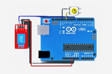
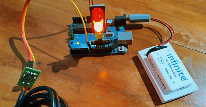
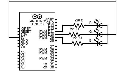
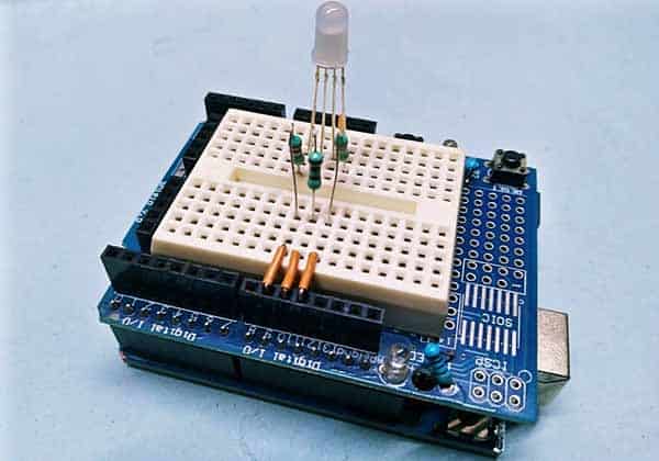
In the quick experiment below, I actually want an Arduino Uno to control the RGB colors through a potentiometer. In order to do so, I’m simply using a regular 10K potentiometer and a common-cathode RGB LED. Here’s the simplified hardware setup diagram:
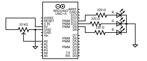
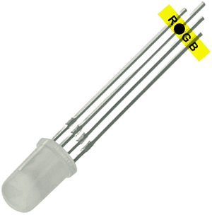
And, the pin notation of a common-cathode RGB LED. This one is a “diffused” type RGB LED that shines through a translucent dome, thus renders a more uniform light spread.
The Arduino Sketch is rather simple. Actually, it’s the mere adaptation of a nifty code posted by someone on the web (I could not find more details about the coder).
const int redPin = 11;
const int greenPin = 10;
const int bluePin = 9;
const int potPin = A0;

int currentColorValueRed;
int currentColorValueGreen;
int currentColorValueBlue;

void setup()
{
	pinMode(redPin, OUTPUT);
	pinMode(greenPin, OUTPUT);
	pinMode(bluePin, OUTPUT);
}

void loop()
{
	int potPinValue = map(analogRead(potPin), 0, 1024, 0, 255);

	if (potPinValue <= 42.5) {
		currentColorValueRed = 255;
		currentColorValueGreen = potPinValue * 6;
		currentColorValueBlue = 0;
   }

   if ((potPinValue > 42.5) && (potPinValue <= 85)) {
		currentColorValueRed = 255 - (potPinValue - 43) * 6;
		currentColorValueGreen = 255;
		currentColorValueBlue = 0;
   }

   if ((potPinValue > 85) && (potPinValue <= 127.5)) {
		currentColorValueRed = 0;
		currentColorValueGreen = 255;
		currentColorValueBlue = (potPinValue - 85) * 6;
   }

	if ((potPinValue > 127.5) && (potPinValue <= 170)) {
		currentColorValueRed = 0;
		currentColorValueGreen = 255 - (potPinValue - 127.5) * 6;
		currentColorValueBlue = 255;
	}

	if ((potPinValue > 170) && (potPinValue <= 212.5)) {
		currentColorValueRed = (potPinValue - 170) * 6;
		currentColorValueGreen = 0;
		currentColorValueBlue = 255;
	}

	if ((potPinValue > 212.5) && (potPinValue <= 255)) {
		currentColorValueRed = 255;
		currentColorValueGreen = 0;
		currentColorValueBlue = 255 - (potPinValue - 212.5) * 6;
	}

	analogWrite(redPin, currentColorValueRed);
	analogWrite(bluePin, currentColorValueBlue);
	analogWrite(greenPin, currentColorValueGreen);
}
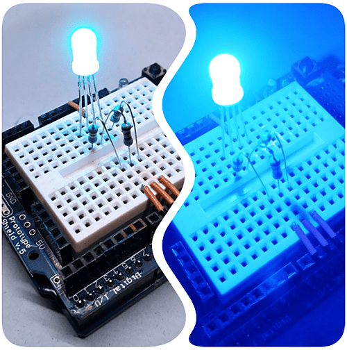
Now you can crossfade between Red, Green, and Blue.
Look, at the minimum potentiometer setting red is fully on but green and blue are off. As you dial the potentiometer over the first 1/6th, the green fades up to 100%. On the next 1/6th, the red fades out until you only have green. This pattern iterates for green to blue transitions, and at last for blue to red stopping at the start point of full red. Next is a slightly different Arduino Sketch for making a simple RGB LED mood light with one common-anode RGB LED. In this code, each of the functions starts with a beginning color, then slowly fades from that color to the next color. This is another adapted Arduino Sketch, originally taken from an Instructables article that I came across some time ago. Actually, I used the original Attiny45 code as a starting point and customized it for my specific hardware configuration (see below).
const byte LED_R = 11;
const byte LED_G = 10;
const byte LED_B = 9;

void setup() {
  pinMode(LED_R, OUTPUT);
  pinMode(LED_G, OUTPUT);
  pinMode(LED_B, OUTPUT);
}

void loop() {
  redtoyellow();
  yellowtogreen();
  greentocyan();
  cyantoblue();
  bluetomajenta();
  majenatored();
}

void redtoyellow() {
  digitalWrite(LED_R, LOW);
  digitalWrite(LED_B, HIGH);
  for (byte i = 1; i < 100; i++) {
    byte on = i;
    byte off = 100 - on;
    for ( byte a = 0; a < 100; a++ ) {
      digitalWrite(LED_G, LOW);
      delayMicroseconds(on);
      digitalWrite(LED_G, HIGH);
      delayMicroseconds(off);
    }
  }
}

void yellowtogreen() {
  digitalWrite(LED_G, LOW);
  digitalWrite(LED_B, HIGH);
  for (byte i = 1; i < 100; i++) {
    byte on = 100 - i;
    byte off = i;
    for ( byte a = 0; a < 100; a++ ) {
      digitalWrite(LED_R, LOW);
      delayMicroseconds(on);
      digitalWrite(LED_R, HIGH);
      delayMicroseconds(off);
    }
  }
}

void greentocyan() {
  digitalWrite(LED_G, LOW);
  digitalWrite(LED_R, HIGH);
  for (byte i = 1; i < 100; i++) {
    byte on = i;
    byte off = 100 - on;
    for ( byte a = 0; a < 100; a++ ) {
      digitalWrite(LED_B, LOW);
      delayMicroseconds(on);
      digitalWrite(LED_B, HIGH);
      delayMicroseconds(off);
    }
  }
}

void cyantoblue() {
  digitalWrite(LED_B, LOW);
  digitalWrite(LED_R, HIGH);
  for (byte i = 1; i < 100; i++) {
    byte on = 100 - i;
    byte off = i;
    for ( byte a = 0; a < 100; a++ ) {
      digitalWrite(LED_G, LOW);
      delayMicroseconds(on);
      digitalWrite(LED_G, HIGH);
      delayMicroseconds(off);
    }
  }
}

void bluetomajenta() {
  digitalWrite(LED_B, LOW);
  digitalWrite(LED_G, HIGH);
  for (byte i = 1; i < 100; i++) {
    byte on = i;
    byte off = 100 - on;
    for ( byte a = 0; a < 100; a++ ) {
      digitalWrite(LED_R, LOW);
      delayMicroseconds(on);
      digitalWrite(LED_R, HIGH);
      delayMicroseconds(off);
    }
  }
}

void majenatored() {
  digitalWrite(LED_R, LOW);
  digitalWrite(LED_G, HIGH);
  for (byte i = 1; i < 100; i++) {
    byte on = 100 - i;
    byte off = i;
    for ( byte a = 0; a < 100; a++ ) {
      digitalWrite(LED_B, LOW);
      delayMicroseconds(on);
      digitalWrite(LED_B, HIGH);
      delayMicroseconds(off);
    }
  }
}
Arduino is of course a great platform for prototyping our projects quickly. Once I’m ready to finalize my mood light build, though, the regular Arduino board seemed a bit beefy, and I wanted to free it up for my next-level experiments.
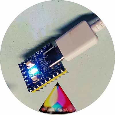
So, I choose an Arduino Pro Mini (5V/16MHz) and it’s a perfect pick for my small mood light project. Later, in my search for another small (and unique) microcontroller board, I came across the Waveshare RP2040-Zero. Two things make it perfect for my project – First, it’s a lovely form factor. Second, it features an onboard WS2812B LED.
Another fancy light project based on this pretty cute “Raspberry Pi Pico” microcontroller board will be published later. In the meantime, try to play around with Hunor Marton’s HSL Color Picker (https://codepen.io/HunorMarton/pen/dvXVvQ/), and create something incredible yourself!