What is Potentiometer?
Potentiometer or Rheostat is one type of passive variable resistor (variable potentiometer) either carbon or wire wound, with three terminals used to get the desired voltage division. Hence, the name variable voltage divider.
The shaft rotates in a clockwise or anticlockwise direction to tune the voltage. This will enable to control the current flowing in an electric circuit and a change in output voltage or resistance.
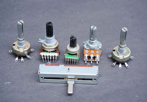
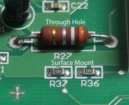
This tuning resistor is manufactured in different forms such as presets, rotary potentiometer, trimming potentiometers, and Rheostat.
In this tutorial, you will learn the definition and working of a potentiometer.
By definition, “Potentiometer” is a combination of the words, Potential Difference, and Metering. Increasing or decreasing the resistance of the potentiometer controls the flow of electric current.
If we increase the resistance of the potentiometer, a large amount of electric current is blocked and only a small amount of electric current is allowed. And if we reduce the resistance of the potentiometer, more amount of current can pass as the resistance offered by the potentiometer would be less.
It is commonly used to control electrical devices such as volume controls on audio equipment and for calibration of voltmeter and ammeter. The construction of potentiometer uses core materials such as wire-wound, carbon composition, metal film, and cermet.
The US and European Standard Symbols
In electronic circuits, To represent the symbol of the potentiometer and presets following diagram is shown.
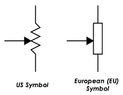
It has a resistor with an arrow connected to it. It indicates that the arrow can be varied slowly. This will increase or decrease the resistance.
Before using the pot, its features and characteristics must be known for proper installation.
Potentiometer Characteristics
Every potentiometer has these common characteristics and the user must choose the right one for a suitable application.
Electrical Taper
The taper determines the ratio of resistance between the wiper control and the contact resistor. To represent the ratio the pot uses a linear or logarithmic scale. The X-axis scale shows the percentage output and the Y-axis scale shows the number of degrees the wiper rotates in clock-wise or anti-clockwise position.
Label Marking on Body
The body surface has a marking code to know the maximum resistance for tuning. For instance, a pot with marking 10K (103 code) has an upper maximum threshold of 10K. This value varies from one manufacturer to another manufacturer.
Power rating
The power rating of potentiometer tells the ability of how many watts it can handle. The maximum power rating or power dissipation is :
Power dissipation of potentiometer = (V2) × [Resistance of Pot + Load impedance/Resistance of Pot * Load impedance]
Where ‘V‘ is the applied DC voltage in volts.
Element Consideration
The type of element decides the construction of a potentiometer. The material is Wirewound, Hybrid, conductive plastic, and Cermet and graphite type.
The Wirewound element uses a single turn and multiturn style, cermet has good resistance strength and the conductive plastic model has better noise characteristics.
Resolution
This characteristic defines the amount of change in output voltage when the shaft rotates. The resolution must be infinite and reduces jitter in amplifiers. This will output large gains for audio and position sensing circuits.
Standard Resistance
The resistance of potentiometer typically varies from 1K to 50K and each resistance has its resistance code on their body.
| Resistance (Ω) | Code Representation (on body) |
|---|---|
| 1K | 102 |
| 2.5K | 252 |
| 5K | 502 |
| 10K | 103 |
| 20K | 203 |
| 50K | 503 |
Number of Turns and Gangs
The number of turns in a potentiometer includes single or multiturn. This feature is useful for measuring distance, rotation angles. Coming to the gangs, single, dual, and flat types exist.
The single gang or single turn pots have a wiper that rotates one turn. Whereas, the dual-gang potentiometer consists of two pots connected in parallel on the same shaft. The pot has equal resistance and taper.
Working of Potentiometer
The potentiometer has three terminals and is used in a large variety of electrical and electronic circuits. To understand, how potentiometer works? We use the resistance principle. It is a rotary device that varies the resistance value by dividing the voltage.
The simplest way to divide the voltage is to take a wire-wound resistor and fit sliding contact with it. The below figure shows the pot (variable voltage divider) consisting of a wire wound resistor with sliding contact (adjustment shaft).
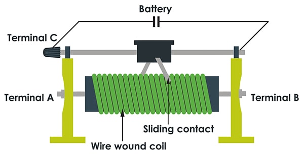
When the sliding contact is at position ‘A‘, the resistance between the terminal A and the sliding contact is more like that for terminal B and sliding contact. The voltage between the terminal B and sliding contact is half.
For example, if the total battery voltage is 100V, the voltage across terminal B and the slider is 40V and the voltage between terminal A and sliding contact is 60V. By moving the sliding contact towards terminal A, the resistance decreases. Now, the voltage will be more at terminal B. In this way, it divides the voltage.
Difference between Potentiometer and Rheostat
A potentiometer is normally called as pot and it has three terminals. The pot ends are connected across the battery source.
To know how potentiometer is used as a rheostat, three pinouts are used. Out of three pins, only two pins are used. One terminal is the outside pin with knob or screw and another terminal is the middle one.
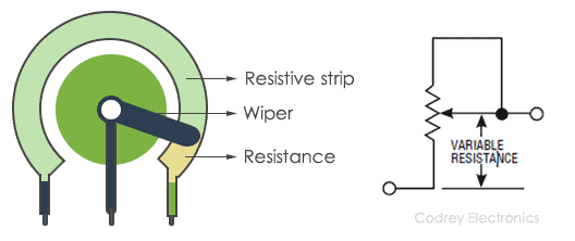
By varying the wiper, the resistance changes. There are different types of potentiometer ranging from 1Ω to several Kilo ohms (5, 10, and 100) and maximum resistance of 10MΩ.
If the wiper is present at the lowest position the output resistance is more and if the wiper is kept at the highest position the resistance is less. In this way, a variable resistor can act as a rheostat.
We can use a potentiometer as voltage divider also, by using the three terminals. As shown below the wiper gives the output voltage, and other terminals are connected to a battery VCC and GND.
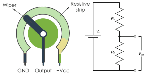
Generally, the knob is connected to supply (+VCC) and the center pin is connected to ground (GND). The wiper contact is varied to get the required output voltage.
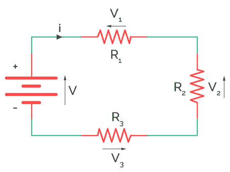
To increase the voltage, turn the knob in the anti-clockwise direction, and to reduce the voltage turn the knob in a clockwise direction. In this way, the voltage is controlled. The voltage divider can be thought of as two resistors connected in series with a battery.
The voltage (Vout) is taken between the two resistors R1 and R2. The formula to calculate the output voltage for a voltage divider using ohms law is
Vout= Vin × R2/ (R1+R2) where Vin is the Input DC voltage of the battery.
By using this above formula, we can determine the output voltage for a given input voltage and resistors.
Potentiometer Example
To understand the application of potentiometer in the real world, this example circuit gives an idea of how to use trimmer pot with an LCD (Liquid Crystal display).
In most of the Human-machine interface (HMI) applications, LCDs display the data and interact with the user. But, to show the characters in a clear format, brightness and contrast must be set using a potentiometer. The LCD uses a 10K potentiometer (POT) to change the brightness.
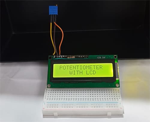
To control the brightness of the backlight we can use the third pin (contrast) of 16×2 LCD by rotating the potentiometer knob in a clockwise or anticlockwise direction. The first pin of LCD is ground and the second pin is the VCC (5V). Now, the connection of potentiometer with LCD is:
LCD 1st pin (Ground) – potentiometer 3rd pin
2nd pin of LCD (VCC) – 1st pin of the potentiometer
LCD 3rd pin (VEE) – potentiometer 2nd pin (Wiper)
Other than this, for the proper working of LCD short the 1st pin and 16th pin (cathode) of LCD and add 10Ω resistor for the 2nd (VCC) and 15th pin(anode).
Types of Potentiometer
Here is the short comparison of different potentiometers and their applications.
| Potentiometer Type | Description | Applications |
|---|---|---|
| Rotary pot (single-turn or multi-turn) | Turn the spindle or knob to control the pot | Fan regulator, Power Supply, Volume control in Guitars, and Audio circuits. |
| Trimming potentiometer (or Multi-turn Trim pot) | Easy to calibrate the circuits on PCB with a screwdriver | Mounted on PCB boards for fine-tuning with a screwdriver, to vary the voltage, Used in LCD to adjust contrast and brightness, signal gain adjustment |
| Slide pot (slider) | Also known as fader potentiometers. Move the fader to change the resistance | Mixers, Equalizers, Audio electronics |
| Membrane potentiometer | These flat in structure. When pressure is applied to the membrane the resistance of the pot varies. | Manual adjustment |
| String potentiometer | Converts the action of a movement into an electrical signal | Displays, Data logging devices |
| Digital Potentiometer | Replacement for mechanical potentiometers | Used in Data Converters |
| Linear pot | Movement detection of the position | The transducer, Automated controllers, Audio, Robotics |
Summary
In short, a conventional potentiometer is a mechanical-electrical transducer that uses graphite material and has three terminals. It has a wiper connected to the 1st and 3rd terminal. When the wiper on the potentiometer rotates, the resistance changes, and thus it reflects in the second terminal.
For single-turn pots, this wiper typically travels just under one revolution around the contact. “Multiturn” potentiometers also exist, where the resistor element may be helical and the wiper may move 10, 20, or more complete revolutions.