How is the Resistance Measured?
To measure an electrical resistance (Low resistance, Medium resistance, and High resistance) electronic instruments use two measurement techniques. They are constant voltage and constant current.
The constant voltage method measures high resistance which passes a known voltage to determine current across unknown resistance. This method is efficient than a constant current method as we can apply various test voltages to find out unknown resistance.
Whereas, the constant current method passes a known current to a resistance which is not known. From this, the voltage is measured. To measure high resistance(200MΩ), we can use the constant current technique. Digital Multimeters (DMM) use this type of implementation.
Now, let’s discuss how to measure resistance.
Resistance Measurement Methods
Measuring resistance helps to know the maximum values for resistance elements such as Manganin, Copper, Nickel, etc. The resistance readings range from few microohms to several megaohms.
We can connect voltmeter and ammeter in a circuit to determine low resistance and high resistance in a circuit. They are a bridge method and fall of potential.
The bridge connection method uses a Galvanometer and a simple resistor with high precision. Some of the bridge type resistance measurements are Wheatstone bridge, AC impedance, and Kelvin double bridge.
The fall of potential method uses voltmeter and ammeter for resistance measurement. The voltmeter calculates the voltage and ammeter measures the current. From the ohms law, we can evaluate the resistance.
How to measure Low Resistance (<1Ω)
Low resistance is found in switches, copper windings, transformer windings, circuit breaker contacts, battery strap connections, motor windings, etc.
To understand how to make a low resistance measurement less than 1Ω, three methods are used. They are potentiometer, voltmeter-ammeter, and kelvin bridge.
Potentiometer method
The DC potentiometer method measures the unknown resistance by taking fixed or standard resistance as a reference value. A rheostat changes the resistance and controls the current ‘I‘ in the circuit. An ammeter is connected in series with the unknown and standard resistance.
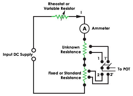
When DPT switch is at position 1, it controls the unknown resistance and when it is at position 2 it controls the standard resistance. The voltage drop across the resistance is taken as output using ohms law. Hence the unknown resistance is given by
Unknown resistance = (Voltage drop across Unknown resistance/Voltage drop across Standard resistance) * Standard resistance
Voltmeter – Ammeter method
The voltmeter – Ammeter method measures the low resistance with an accuracy of ±1%. To achieve one percent tolerance, it uses four terminals for measurement. Two of them are current terminals (C1, C2), and the remaining two are potential terminals (V1, V2).
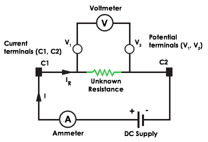
There will a less voltage drop across potential terminals and the current flows in and out from the unknown resistor. The contact resistance is small at the current terminals and the unknown resistance is calculated from the voltage drop across voltmeter and current through the ammeter.
Kelvin Bridge
The Kelvin bridge (Thomson Bridge) measurement has the benefit of canceling the extra resistances from the test leads and contacts. The below figure shows the kelvin double bridge circuit.
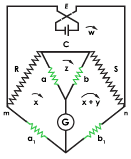
The bridge uses double ratio arms to nullify the resistance. ‘R‘ is the unknown resistance and ‘S‘ is the standard resistances of low value. ‘C‘ is a heavy copper connection. The branches a, b, a1, and b1 are high resistances values when compared with ‘R‘ and ‘S‘.
The kelvin double bridge equation is given by the formula
R/S = (a1/b1) – {C/S × (b/(a+b+C)) × (a1/b1 – a/b)}
For correct measurement, the ratio of ‘R‘, ‘S‘, and a, b must be equal. Now, the circuit is in balance condition. This will deflect the current in Galvanometer ‘G‘. This bridge measures the resistances in the range from 0.1 ohms to 1 ohm.
Medium Resistance Measurement (1Ω -100KΩ)
Ammeter Voltmeter
The Ammeter-Voltmeter method works using two configurations. In the first setup, connect the ammeter in series with the unknown resistance. This method measures the correct value of the current through the unknown resistance ‘R‘.
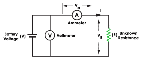
The voltmeter equals the sum of the current across ammeter and voltage across resistance ‘R‘. To measure resistance output (Rm), the value of resistance ‘R‘ must be greater than the resistance of ammeter (Ra). Hence this method is suitable for measuring medium resistances.
The true value of measured resistance is Rm = R+Ra. To get exact resistance, the ammeter resistance must be zero. This is true in the ideal case.
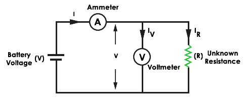
In the second configuration, connect the voltmeter in parallel with the unknown resistance. The voltmeter measures the correct voltage. But here the ammeter measures the sum of the currents flowing through the voltmeter and unknown resistor. In the ideal case, the voltmeter resistance is infinite to get true voltage output.
The error at full scale for the ammeter voltmeter method is about 0 to 1%. Hence the Wheatstone bridge is preferable.
Wheatstone Bridge
The Wheatstone bridge is an old method and is no longer in practice. But it tells the concept of a balanced bridge to measure unknown resistance. The bridge has diamond shape grouping which consists of four resistances A, B, R, and S. The resistance B and S are fixed resistances.
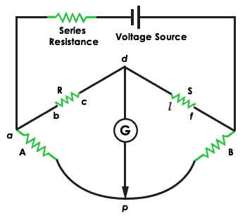
The voltage is applied to the input terminals ‘a‘ and ‘s‘ and the galvanometer (also known as a null detector) is connected to the output terminals ‘p‘ and ‘d‘. To measure the resistance ‘R‘ using Wheatstone bridge vary the standard resistance ‘A‘ until the current in the galvanometer reads zero current reading. This proves that the bridge is present in a balanced condition.
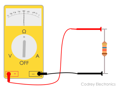
Resistance Measurement Using Ohmmeter
Here are steps on how does ohmmeter work to measure the resistance of a resistor or some component.
- The first important step is to do is turning off the circuit (To ensure the accuracy in measurement and not to damage the circuit, disconnect the power to the circuit)
- Place the probes on the respective sockets:
- Insert the black probe to the common (COM) port of the multimeter
- Insert the red probe to the voltage (VmAΩ) port of the multimeter (Red terminal)
- Zero the meter by placing the two probes touching together and adjust the dial or knob by turning it until it shows zero ohms
- Test the resistance of the component using the two probes by placing at each side
- Turn the knob to the relevant ohms range you are trying to measure. (If the pointer deflects to the right side of the scale, decrease the range to one level. If the pointer deflects to the left side of the scale, increase the range to one level)
- Take the reading on the scale and multiply it with the appropriate range on the dial.
- Make the ohmmeter zero again before testing another component.
Note: Always check for the resistances connected in parallel. The multimeter computes the resistance between the different paths in a circuit.
The multimeter measures the total resistance in a circuit through all possible paths. It’s always better to remove the component to measure the resistance. Otherwise, the multimeter will show wrong resistance reading.
High Resistance Measurement (>100KΩ)
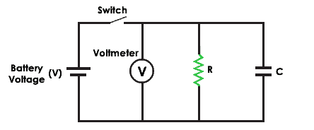
Loss of charge method
The resistance measurement by using the loss of charge method uses an unknown resistance (R) in parallel with the voltmeter and a capacitor (C). When applying the DC voltage, the current flows through the circuit and the capacitor charges until the battery voltage. After that, it discharges through the resistance ‘R’.
The equation for voltage across the capacitor is v = V.e(-t/CR)
The resistance equation ‘R‘ is equal to 0.4343t/ (C log10 V/(V-e))
Megger Circuit
The use of megger is to measure high insulation resistance in a circuit. The below figure shows the circuit of megger. It uses a hand-driven generator which produces a voltage of 500V, 1000 and 2500V.
The generator incorporates an automatic clutch that uses the centrifugal principle to operate the instrument. The generator supplies a constant voltage to measure the low insulation resistance.
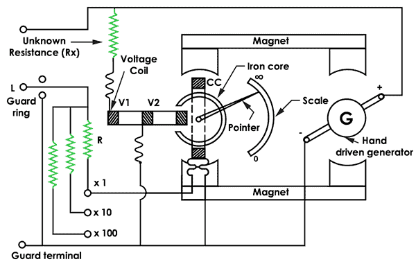
The megger has three coils (2 voltage coils and 1 current coil). The current coil moves in the clockwise path and the voltage coils in the counterclockwise. The two coils make the pointer set it to the middle position. Now, you can apply the voltage and measure the resistance.
The pointer scale becomes steady by connecting a resistance under test (Unknown resistance Rx).
Megaohm Bridge method
The megaohm bridge measures high resistance from 0.1 megaohms to 1 megaohm. The guard terminal is connected to the galvanometer (G). The multiplier switch is used to select the range of resistances to be measured.
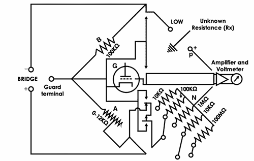
A fixed resistance of 100 KΩ and connecting a guard terminal to a guard circuit removes the leakage resistance.
Difficulties in reading resistance
- The human body absorbs current, hence make sure to avoid contact with the component when measuring with multimeter or ohmmeter.
- Test the components individually to get correct resistance.
- Don’t measure the resistance in a power-on circuit. This will give wrong readings.
Tip: Power off the circuit and measure the resistance.
- Check the damage of the component (shows zero resistance in multimeter).
- Repeatability to measure low resistance within a few micro ohms. This will impact the current consumption in an electrical circuit.
Conclusion
Nowadays, there are multiple methods for resistance measurement. Among them, LCR meter and digital low resistance ohmmeters supersede with the Wheatstone bridge, Kelvin double bridge, and other methods. Hence it is necessary to select a proper instrument for testing the resistance.