Relay is an electromechanical switching device most widely used in the automotive and telecommunication industries. It can be found in cars, washing machines, medical equipment, aircraft, etc. We can see that relays are being used in control systems and power systems industries to protect the system or load circuit from unexpected damage.
By definition, Relays are electrically operated devices which can open or close the contacts electrically. It can be used to turn ON or OFF (make or break) the circuits or where several circuits must be controlled by one signal or high-power circuits that can be controlled by low power signals.
A protective relay is a device that detects the fault (any abnormal state in the power system is known as fault) and initiates the operation of the circuit breaker to isolate the faulty element from the rest of the healthy power system.
Relays are useful when there is a need to control large current or voltage by a low power signal. They come with different functions and types. It generally consists of electromagnets that control the circuits electromechanically to make or break the load circuit.
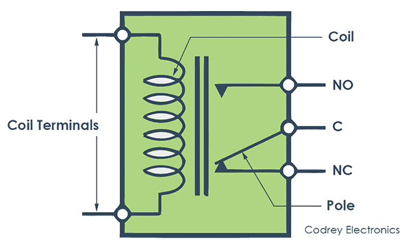
Relay terminology
The application of electrical relay can be understood using the below parts. It consists of
Pole – Several isolated circuits that a relay can switch
Throw – A number of closed contact positions per pole
Contact form– The number of contacts and contact mechanism
Normally open– In this position, the contacts will connect the circuit (close) when the relay is actuated.
Normally closed– Here, the contacts will disconnect (open) when the relay is actuated.
Changeover contact– It can control two circuits. One terminal is normally open and normally closed contact with a common terminal.
Contact rating or Power rating: This specifies the amount of power the relay can switch a device that is connected as load. The relay ratings should be considered while using a relay for AC and DC switching. For example, a relay operated with 12V DC and current rating of 10Amperes can switch less than or equal to 10A.
Voltage: A source voltage to be applied to the coil
Current: The amount of current flow in the relay when the nominal voltage is applied
Construction
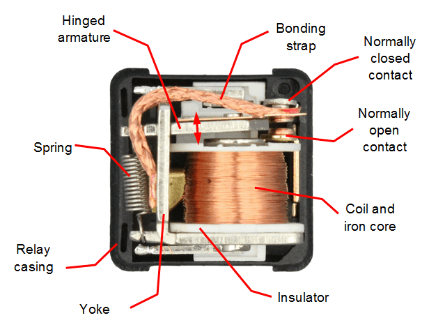
The relay construction comprises of various mechanical parts that are located inside the outer casing. The mechanical parts of the relay have an Electromagnet, Movable Armature, Contacts and spring.
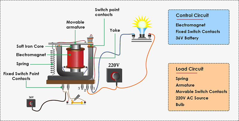
From the above diagram, the relay has two circuits namely control circuit and load circuit which are physically isolated. The control circuit has an electromagnet, Fixed Switch contacts, and the load circuit has movable switch contacts, movable armature, spring and the load (Bulb) to be actuated.
The most important part of the relay is the electromagnet. It is a soft iron core wounded by a coil. It doesn’t have the magnetic property initially. But it can acquire the properties of a magnet when a voltage is applied to the coil winding. Because when a voltage is applied to a metal winded with copper wire, it can act as a magnet.
The movable armature can make or break the contacts. The spring can keep the contacts separated until the electromagnet is energized.
It has normally closed, normally opened terminals and a common terminal. When the coil is not energized, the normally closed terminal is connected to a common terminal or to the armature, and the normally opened terminal is left free.
How does a Relay Work?
The relay operating principle is, when a voltage is applied to the electromagnetic coil, it magnetizes the iron core and generates the magnetic field which attracts the armature towards it. This makes the contact to close (closing the load circuit) or open in case if it is normally closed relay (depends upon the construction).
When the voltage is removed, the spring will push the contacts away, which breaks the load circuit.
We can see an example of the relay circuit. Here the relay will turn on an AC lamp and a switch will trigger the relay when the armature is closed.
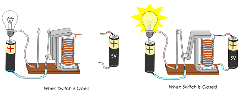
In the above circuit, the 5V relay is powered by a 5V battery. An ON/OFF switch is for the switching purpose of the relay. At the initial condition the switch is open, no current will flow through the coil, so the contact normally opened terminal is open.
When the switch is closed, the current starts flowing through the coil, and the magnetic field is generated in the coil which attracts the movable armature which will close the normally closed terminal. Hence, the lamp turns ON. So, we can control a high-power circuit through a low power signal using a relay.
Classification
The relay switch is classified by their number of poles and throws and they include SPST, SPDT, DPST, DPDT etc.
SPST
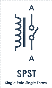
SPST (Single Pole Single Throw) relays have two terminals that can be connected or disconnected and two more for the coil. So, four terminals in total. It can control only one circuit at a time its either opened or closed.
SPDT
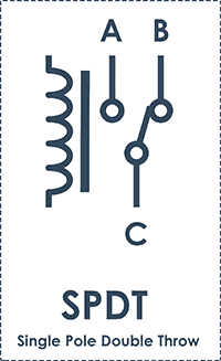
In this type of relays (Single Pole Double Throw), a common terminal connects to either of two other terminals and two more terminals for the coil. It can control only one circuit at a time because of its single-pole but it has two throw positions to conduct. When one circuit is opened, the other circuit remains closed and vice versa.
DPST
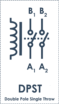
This type of relay (Double Pole Single Throw) has six terminals. This is equivalent to two SPST relays actuated by a single coil. The double pole can control two completely isolated circuits. Single throw has only one position.
So DPST relay can switch two circuits simultaneously by providing either close or open circuit.
DPDT
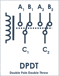
This relay (Double Pole Double Throw) has eight terminals. These have two change-over terminals and This is equivalent to two SPDT relays actuated by a single coil. Double pole and double throw represent that it can control two circuits and can conduct in two separate positions respectively.
Types of Relay
Based on the principle of construction and function, there are different types of relays categorized as
- Electromechanical relay (EMR)
If multiple circuits have to be controlled with a single trigger pulse, then electromechanical relays are the best choice. Electromechanical relays have switch contacts and use electromagnetic force to mechanically open and close the contacts to turn ON/OFF. The advantage is it requires less resistance to switch current and doesn’t need a heat sink. Moreover, they are less prone to electric shock and are fail-safe. The only disadvantage with EMR is wearing out quickly.
- Solid State Relay (SSRs)
The advantage of Solid-state relays over electromechanical relay is, they do not have the mechanical moving parts. Instead, they consist of semiconductors and electronic parts such as optocouplers. Solid-state relays turn ON/OFF signals, currents, or voltages electronically by the operation of these electronic circuits. A Solid state relay or MOSFET relay works by the principle of a simple switch. When power is applied to one terminal and control signal is passed through another terminal, the load connected to the relay circuit will turn on and turn off quickly with the help of MOSFET transistor. Then, current will be blocked when the relay is in off state and allows the current when a control signal is triggered.
SSRs are used for both AC and DC switching applications. The DC relays operate using a single MOSFET transistor which allows higher current and AC relays uses two MOSFET transistors to drive current in both directions (positive half cycle and negative half cycle).
- Microprocessor/Numerical relay
Uses microprocessor type relays for switching purposes. The electrical faults are detected using software testing algorithms and diagnostics communication etc. The microprocessor detects over voltage and current, frequencies, ground faults, excitation loss of power etc.
How to Test a Relay?
Step 1:
Check in the datasheet. This is the best way to inspect relay pins and their connections. The datasheet will contain current and voltage ratings which will help to use the relay without damaging. The relay details are provided on the body itself.
Step 2:
Check the relay physically. Modern switches come up with LED. When the relay is present in an active state, the LED will glow and it will make a click sound.
Step 3:
Use a Digital Multimeter for testing relay (DMM). As we know it consists of two contact terminals, Normally Closed (NC) and Normally Open (NO).
In de-energized condition, check the resistance between the NO terminals, it should be infinite ohms (practically in Mega Ohms). And, the resistance between the NC terminals should be zero ohms.
Now, apply the required voltage to energize the relay. Check the NC contacts, they will show infinite resistance in Digital Multimeter(DMM) and zero ohms between NO contacts.
Things to consider:
- Life
- Reliability
- Redundancy/Backup
- Simplicity in function
- Power draw (on the battery)
- Cost
- Calibration/Maintenance
- Speed & Accuracy
- Flexibility
- Current/Voltage inputs
Relay Applications
Here are some of the important applications of relay that are used in automation, energy, smart grid, telecom, and power industries.
- Relay isused for ON/OFF applications
- Capable of switching multiple circuits
- Coil relays are used for the protection of circuits
- Controls high power circuit with a low power signal
- For home appliances such as refrigerators, washing machines
- For moulding equipment, packing machinery, vending machines
- They are used in Motor & lighting control
- Used in Aerospace, Defense, and automotive industries
- Used in the traffic signal controllers, temperature controllers, heaters
- When the supply voltage is other than the rated voltage, a set of relays sense the voltage variations and controls the load circuit with the help of circuit breakers.
- Solid-state relays use power semiconductor devices such as transistors and thyristors to switch currents up to 100 amps.
- Prevention of non-directional overcurrent protection and direction control of earth faults.
Conclusion
In short, Electronic overload relays are essential protection components for over current and current sensitive applications such as motor overloads, high inrush currents and stalled motor problems. Moreover, they are helpful in monitoring electrical parameters like temperature, line currents, power factor and residual currents.
Other than general purpose ones, HVAC relays (for fan switching), Time delay relays (for flashlight control, self start control in bikes and cars engines, automatic timing control etc), liquid level control relays have resistance detection circuit that senses condensation levels in a tank.