Each new day comes with another chance to see things in a new light. And by all means, don’t be afraid to change your mind. Things get better that way!
I recently purchased a few used linear power supply units from a street merchant ranging up to 10A at 12V. My intention is to power old car audio/video systems, motor horns, battery chargers and similar. However, after a quick inspection, it became ostensible that all lacked any form of crowbar protection. At that moment, my mind headed me back to some old school electronics, and by that nostalgic impulse, I got interested again in thinking, learning, and making crowbar protection circuits.
Crowbar Protection Circuit
Crowbar circuit is a little electronics circuit used for preventing an overvoltage condition of a power supply unit (PSU) from damaging the circuits attached to its output. It operates by putting a short circuit (low resistance path) across the output of the PSU. An example crowbar circuit is shown below. See also https://en.wikipedia.org/wiki/Crowbar_(circuit)
Looking at today’s crowbar schematics online and studying many of them, I thought of some other, perhaps odd, simple crowbar designs for everyday application. Finally, I managed to get the time to write it up. These are just my random thoughts coupled with a number of crude crowbar circuits. So, welcome back to my workbench!

Design Idea 1
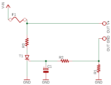
You may think there is a simple solution – a fuse. We all know fuses are imprecise and can be dangerous if they don’t act in the right time and blow properly. This first circuit idea is very simple to implement and to tweak to your own requirements. In the circuit, the current sense resistor (R1) will develop a voltage which is proportional to the load current. The RC stage (R2/C1) provides a low pass stage to ensure the thyristor (T1) is not triggered by any small variation in the load current. When the thyristor is triggered, then R3 (a wire wound resistor) will shunt heavy current instantly and blow the fast fuse (F1). Note that there’s also a chance that the current sense resistor (R1) blows away if you use an inappropriate one – it must be a ‘healthy’ (and precise) shunt resistor that will not catch fire.
Design Idea 2
Now to the second crowbar circuit idea. In this circuit, when the power supply voltage goes above the threshold voltage of the zener diode (ZD1) current starts to flow through the zener diode and the resistor R1. If the supply voltage reaches the zener threshold voltage plus the trigger voltage of the thyristor (T1), the thyristor will trigger to pull the positive supply rail down to the ground rail (actually a small voltage exists there above the ground level). The crowbar will remain active until the power supply is reverted to the previous state. The capacitor (C1) ensures that the thyristor is not triggered mistakenly.
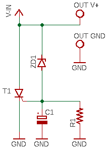
You can see a practical version of this design idea here https://en.wikibooks.org/wiki/Practical_Electronics/Crowbar_circuit
One drawback of this idea is that the crowbar can work only with current-limited power supply sources. Otherwise something there will quite quickly start emitting dense smoke – you may lose everything in the fire if your power source is a crude high voltage/high current PSU!
Besides, the zener threshold voltage cannot be controlled precisely as they’re available only in limited discrete voltages, have a relatively broad tolerance, and the voltage-current knee is not very sharp.
Design Idea 3
Another workable idea is to use a dedicated chip in the crowbar circuit. The MC3423 is such a chip from ON Semiconductor lets you set the trigger voltage between 4.5 V and 40 V using a resistive divider. But it’s somewhat got out. Anyway, this is the simplified application circuit of the MC3423 overvoltage crowbar sensing IC. In order to get more details, refer to the datasheet.
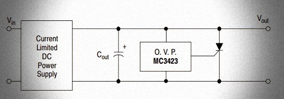
Check out this link to find a real-world amateur radio (ham radio) power supply project that also has a MC3423 at its core http://warc.org.uk/?page_id=404
Also, meet another candidate NTE7172 (https://www.nteinc.com/specs/7100to7199/pdf/nte7172_sm.pdf)
Out of the above three design ideas, you may proceed with the first two if you know what you are doing. The third one might be impractical unless you have a decades-aged junk box that stores dated electronic components. Luckily, I’ve many
It’s clear that one common way to protect a circuit from overvoltages is to use the circuit, that short the power supply rail to ground if an overvoltage is detected and thereby quickly forcing it down to a harmlessly low voltage and blow a fast fuse. The core component in a classic crowbar circuit is the thyristor. The classic crowbar circuit also has some potential drawbacks, and a major concern is the di/dt protection, we can solve the issue at the cost of some additional complexity, though. More details will be included in another related post – in the meantime, you can go through this lucid note http://www.completepowerelectronics.com/scr-thyristor-protection/
Design Idea 4
Although not truly a crowbar circuit, you can build a quick crowbar-style protection mechanism using one electromagnetic relay rather than fiddling with a thyristor.
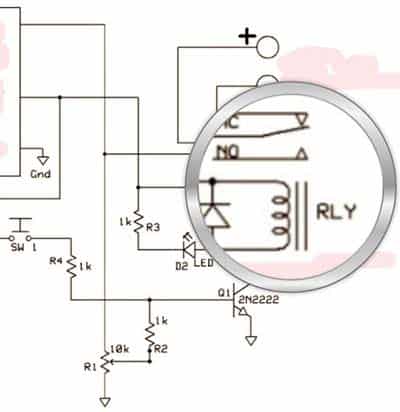
I don’t want to reinvent the wheel. So, I’m sharing the link of the related project now: www.trainelectronics.com/Crowbar/index.htm
Li-ion/LiPo Battery & Crowbar Circuit!
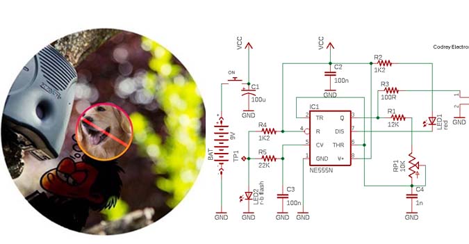
Finally, a quick crowbar-like design (subject to revision) employing the quite popular 3-pin adjustable precision integrated shunt regulator – TL431. The circuit diagram given below is tailored for single-cell (1S/ 3.7-4.2V) lithium-ion and/or lithium polymer battery packs. The circuit is in fact a ‘full-charge’ signaller that can ‘communicate’ with an external device – a battery charger for example. Well, not an adept candidate for a lithium battery pack, but it’ll work.
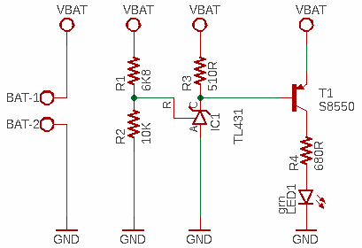
Working of the circuit is extremely simple and straight forward. If the input voltage of the circuit, coming from the battery, reaches 4.2V (the top voltage of a single-cell lithium-ion /lithium polymer battery), IC1 switches T1 to light up LED1. If the input goes below 4.2V, IC1 can see a voltage less than its internal reference voltage (2.5V) on the resistor divider, and therefore it will turn off T1.
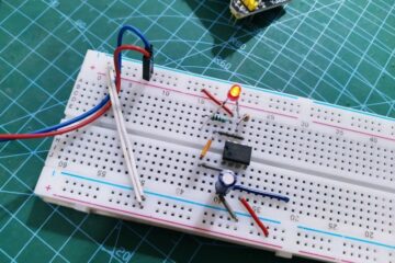
Instead of staying with the debug LED1, you can use an appropriate photocoupler there to switch/control an external device isolatedly. Below you can see my breadboard setup. Not to mention, you should use 1% resistors in this design, especially for R1 and R2. TL431 datasheet https://www.ti.com/lit/ds/symlink/tl431.pdf
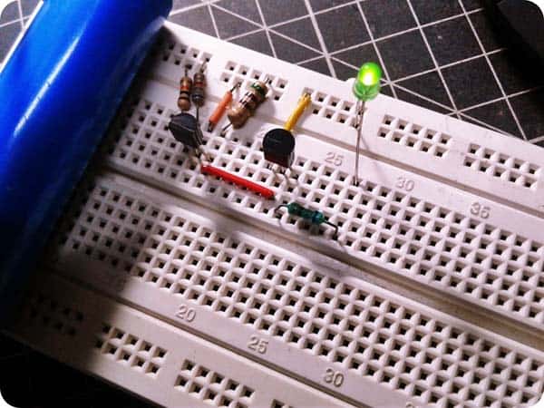
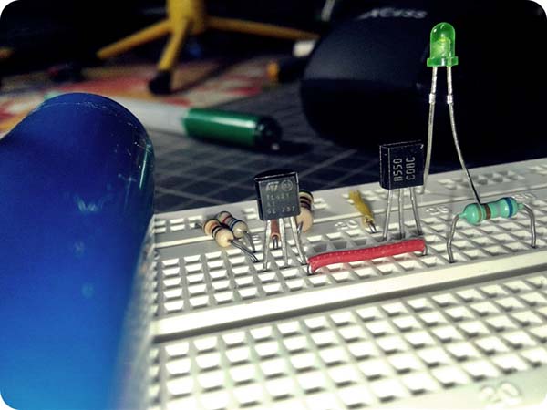
The whole point of the above practical design, containing only a couple of components laying around, is that I can hopefully make quick modifications and experiments. In fact, I’m building a device that also includes a low voltage battery crowbar circuit.
I will tell you all in detail, but later, as I have few things to do before the final implementation. Stay tuned!