As an active electronics hobbyists, I get to see a lot of applications for NeoPixel LEDs. In fact, this new breed of smart LEDs is great for a large number of fabulous hobby projects that previously might have been done with numerous discrete parts or not been done at all because of the high cost and less availability of the needed hardware.
Well, in this post I will show you how to make a fancy NeoPixel LED Light Bar with the help of your favorite Arduino microcontroller. First off, note that here I’m going to focus on developing a pretty simple (but expansible) model. Hopefully, it will be easier to build and perhaps more enjoyable than buying a high-ticket gadget.

Arduino Platform
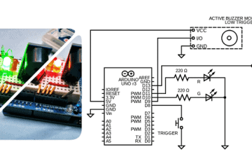
There’re numerous ways to design and build a NeoPixel LED Light Bar but I’m going, to begin with, the simplest solution I know of and the components that are already in stock. Below you can see its hardware setup diagram.
![]()
Keep in mind, it’s okay to power up the Arduino using the 5V and GND pins, but there’s no protection on the Arduino’s 5V connector pin. So, if you apply a voltage higher than 5.5V to the 5V connector pin (or connect that external power backward) many components on the Arduino will be destroyed!
NeoPixel LEDs
As pointed out in the schematic above, the light source used here is a compact “WS2821B-8 RGB LED Stick” containing 8 RGB NeoPixel WS2812B LEDs (see below).
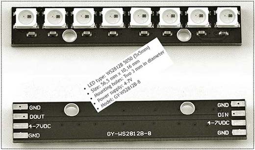
This LED Stick has three connections at each end. One is for +4-7VDC (5V Typical), one for GND (Ground/0V), and one for data. At one end the data pin is marked as DIN and at the other end it is marked DOUT. The DIN pin is connected to the Arduino. The DOUT pins can be connected to the DIN pins on another stick.
Slide Potentiometer
The 10KΩ Linear (10K LIN/10KB) Slide Potentiometer (Slide Pot) employs a resistive element and a sliding contact (wiper) to form an adjustable voltage divider. The resistance of the slide potentiometer can be varied by moving the slider from one end to another. Since the slide potentiometer has two ends, when the slider is at one end the resistance is 0Ω, and moving the slider towards the other end will change the resistance towards 10KΩ as per the slider movement.
Follow this link to get the Panasonic Slide Potentiometer Quick Selection Guide https://www.meditronik.com.pl/doc/plus/aol0000pe1.pdf
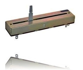
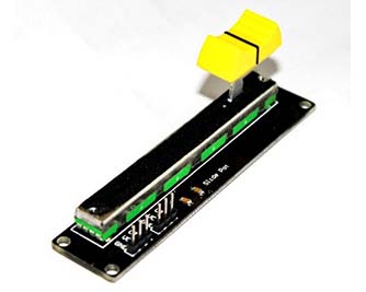
Actually, mine is a prewired slide potentiometer module. The slide potentiometer module incorporates a dual linear variable resistor with a maximum resistance of 10KΩx2 (but only one of them is used here). The three connection pins of each variable resistor are labeled OUT (Pin 1), VCC (Pin 2), and GND (Pin 3). As wired in the given schematic, when you move the slider from one side to the other, the output voltage (OUT) will range from 0V to 5V (or from 5V to 0V).
Arduino Sketch
The below Arduino Uno Sketch (Also compatible with Arduino Nano v3 & Pro Mini 5V/16MHz) is in fact a blend of examples from various online tutorials (prime source of inspiration https://www.mschoeffler.de).
I do not pretend to interpret all of the tricks that’re used by the seasoned coders of the great libraries and sketches but I love what they do!
#include "FastLED.h" // https://github.com/FastLED/FastLED
#define PIN_SLIDE_POT_W A0
#define MAX_SLIDE_POT_ANALGOG_READ_VALUE 1002 // Tweaked!
#define NUM_LEDS 8
#define PIN_LED 3
#define LED_COLOR CRGB::CRGB::FloralWhite
CRGB rgb_led[NUM_LEDS];
void setup() {
  pinMode(PIN_SLIDE_POT_W, INPUT);
  FastLED.addLeds<WS2812B, PIN_LED>(rgb_led, NUM_LEDS);
}
void loop() {
  int value_slide_pot_a = analogRead(PIN_SLIDE_POT_W);
  int num_leds_switchedon = map(value_slide_pot_a, 0, MAX_SLIDE_POT_ANALGOG_READ_VALUE, 0, NUM_LEDS);
  for (int i = 0; i < num_leds_switchedon; ++i) {
    rgb_led[i] = LED_COLOR;
  }
  for (int i = num_leds_switchedon; i < NUM_LEDS; ++i) {
    rgb_led[i] = CRGB::Black;
  }
  FastLED.show();
}
(Note: I used FastLED3.4 & Arduino IDE1.8.13 on my Windows10x64 system)
When this code is transferred to the Arduino setup, the pixels in the WS2812B-8 RGB LED Stick should light up based on the position of the slider/knob.
Power Source Selection
If you are making the same setup as suggested here, you can try to power the entire setup via the Arduino Uno’s USB port. Then an independent 5VDC power supply is not a critical requirement. On the other hand, for a light bar project involving more than two WS2812B-8 LEDs, do not use the Arduino’s 5V output to power them – you must select an external 5VDC/2A+ SMPS (https://www.electroschematics.com/pixel-led/).
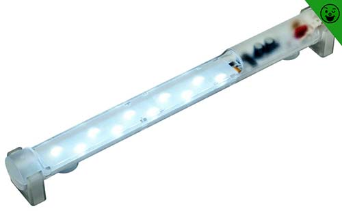
Enclosure Suggestion
A good prototype enclosure will make your build more beautiful. You can rig up one with a 3D printer or choose a ready-made light bar enclosure. See below for inspiration (image from web).
Voltage Translation Issues
On a different note, many microcontrollers nowadays are running at 3.3V instead of 5V. This can introduce a communication problem with some 5V NeoPixels because the advised minimum data input signal voltage is 70% of the NeoPixel voltage (5×0.7 =3.5V).
Luckily, there’re a few ways this can be addressed – the easiest way is to use a 3.3V-5V unidirectional logic level shifter or scale down the NeoPixel voltage somewhat (Low voltage operation is acceptable, with the caveat that the LEDs will be slightly dimmer. Also, there’s a limit below which the LED will fail to light, or will start to display wrong colors).
But while drafting this passage I accidentally read about some inconsistencies between the typical 100kHz logic level shifters and the 5V NeoPixels. So, go through this post first http://www.weigu.lu/microcontroller/tips_tricks/level_shifter_tts/index.html
As discussed in the post mentioned above (where I actually started this sidewalk), the 74HCT125 (https://www.diodes.com/assets/Datasheets/74HCT125.pdf) Quad Tristate Buffer might be a clever pick for 3.3V to 5V logic level conversion (Certainly it’s not actually designed for voltage level shifting, but it will do that task quite nicely).
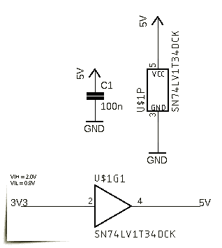
Another great pick is the SN74LV1T34 (https://www.ti.com/lit/ds/symlink/sn74lv1t34.pdf) Single Buffer GATE CMOS Logic Level Shifter!
Voltage Translation – Further Reading https://www.nxp.com/docs/en/nxp/brochures/75017511.pdf
Epilogue: So, I was able to share the crude idea of a simple NeoPixel LED Light Bar. This is actually a blueprint that can be modified a lot. But I leave it to you. Okay, that’s all for now. I hope you enjoyed the post. As always, feel free to suggest any betterment ideas in the comments. Also please let me know what do you think about the aforesaid voltage translation suggestions!
![]()