This little post is about modifying a standard LED Tap Light/Stick Touch Light to run on the Arduino platform with additional features. Okay, let’s get started!
Tap Light?
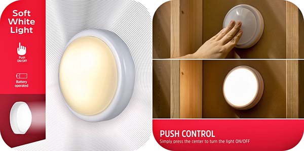
So, what’s a Tap Light? Simply, the battery-powered LED light appears like an opaque acrylic dome with a polystyrene bezel. You can simply use the included double-sided tape or keyhole slot to install it wherever you need it. Then, just push the dome gently to turn the light on and push again to shut it off.
Below you can see the Energizer 36521 Tap Light (https://www.walmart.com/ip/Energizer-Tap-Light-Battery-Powered-Soft-White-Push-On-Off-36521/362485428).
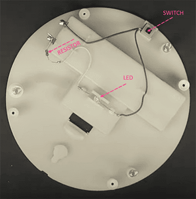
Next is the inside view of a common Tap Light. As you can see below, there’s nothing inside except a small self-locking pushbutton switch and a white LED. Oh, and one more thing – a resistor to limit the LED current. This Tap Light requires 6VDC to run (1.5Vx4 AA battery).
Arduino’s Role!
Fortunately, there’s enough space inside this Tap Light to mount an Arduino Pro Mini board. So, with the help of the Arduino board, we can drive its white LED in some other way. Let me show you a simple hack idea now.
Before getting into that, you need to gather the following parts:
- Arduino Pro Mini 3.3V/8MHz x 1
- Non-Lock Pushbutton Switch x1
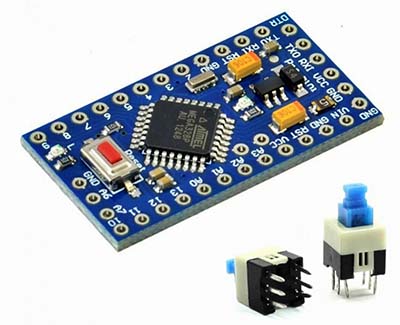
The non-lock pushbutton switch is intended to replace the existing self-locking pushbutton switch as shown in the succeeding schematic.
Quick Diversion!
On a different note, I actually didn’t buy a new Tap Light for this mod because I already have one installed on my lab shelf. But with a second thought, I again bought a very cheap (and a bit different) Stick Touch Lamp(see below). The 3-LED Stick Touch Lamp runs on 4.5VDC (1.5V AAA battery x 3).
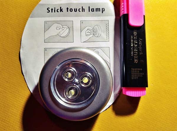
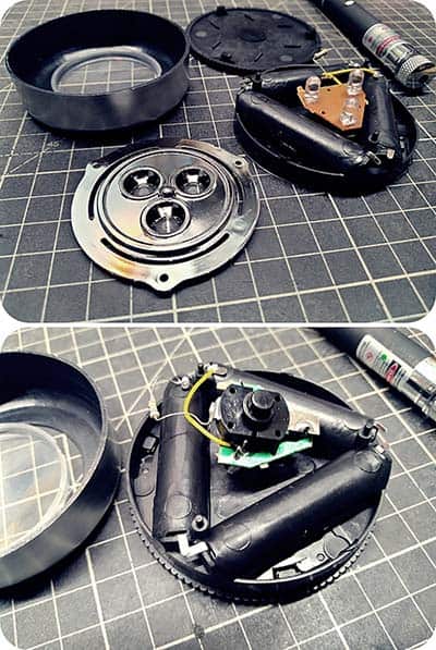
The only problem with the new Stick Touch Lamp is that there’s not enough space inside its casing to hold anything (see below snaps). It’s not a big deal to me as my plan (until now) is to fit the Pro Mini board inside a small project box and mount the Stick Touch Lamp on top of it.
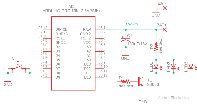
Now look at the “universal” schematic diagram…
…And, the Arduino Sketch for copy-paste-upload!
const int buttonPin = 8;
const int ledPin = 9;
const int fadingDelay = 50;

int buttonState = 0;

boolean fadingState = false;

void setup() {

  pinMode(ledPin, OUTPUT);

  pinMode(buttonPin, INPUT_PULLUP);
}

void loop() {

  buttonState = digitalRead(buttonPin);

  if (buttonState == LOW) {

    if (fadingState == false) {

      for (int i = 0; i <= 255; i += 5) {
        analogWrite(ledPin, i);
        delay(fadingDelay);
      }
    } else {
      for (int i = 255; i >= 0; i -= 5) {
        analogWrite(ledPin, i);
        delay(fadingDelay);
      }
    }
    fadingState = !fadingState;
  }
}
This little code adds a bit of luxury to the modified Tap Light. The first push of the dome will maximize the brightness gradually from zero, and the next push will reduce it to zero. That’s it.
The 100uF capacitor (C1) is a simple buffer capacitor for the RAW supply voltage. Coming to the resistors in the above schematic, R1 is the base resistor of the LED driver transistor S8050 (T1) while R2 is the LED current limiter resistor. You can try a value from 470Ω to 1KΩ for R1, and 39Ω (6VDC input & 1 LED) or 2.2Ω (4.5VDC & 3 LEDs) for R2.
Nevertheless, these values are mere pointers based on my practical experiments. So, you need to do your own calculations as well. Recall, UTCS8050 is a low voltage high current small signal NPN transistor that features a collector current up to 700mA (http://www.unisonic.com.tw/datasheet/S8050.pdf).
You’ll next need to note that 3.3V/8MHz Pro Mini’s RAW is the input voltage that runs into the onboard voltage regulator. The voltage at this input can be anywhere from ~3.4 to 12V. The RAW voltage applied here is regulated to 3.3V before it gets to the processor. For more information on Arduino Pro Mini Programming, check out this page https://www.arrow.com/en/research-and-events/articles/getting-started-with-the-arduino-pro-mini
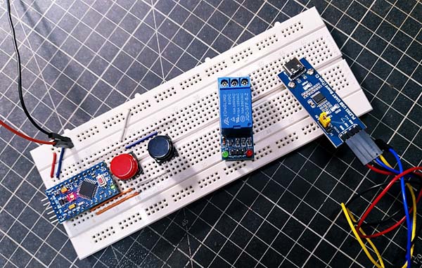
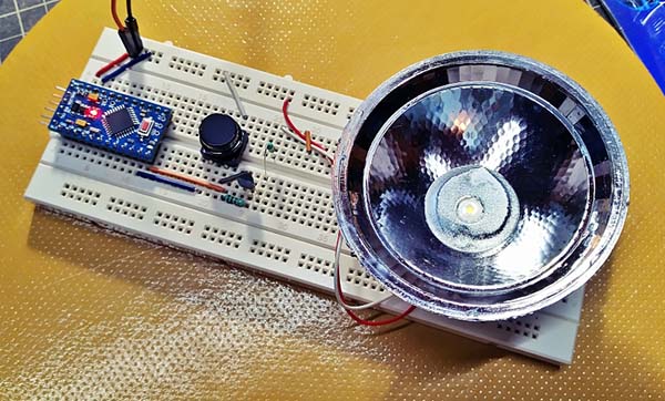
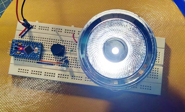
Below is a set of snaps I took while testing the concept on a breadboard. For those experiments, I deliberately used a high-power star white LED to test the ability of the LED driver transistor. It worked smoothly!
Test Setup:
- DC Input: 4.5V (1.5V AAA x3)
- LED Driver Transistor (T1): S8050
- LED: 1W Start White (3.2V/350mA)
- T1’s Base Resistor (R1): 1KΩ ¼ W
- LED’s Series Resistor (R2): 1.5Ω ¼ W
The PWM frequency at D9 as observed is around 245Hz (~5% -95% duty cycle). Look, pins D3 and D9 have ~500Hz on 16MHz but it’s ~250Hz on 8MHz. So, that’s all good and well!
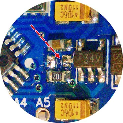
Oh, and before I forget: Pro Mini’s onboard power status indicator is a big nuisance when running the system on battery. You can of course wipe off the minuscule part, but do not try to cut its circuit tracks – just desolder the SMD LED carefully.
In Conclusion…
Yup, I just opened up a way to mod a common LED Tap Light. There’s still room for betterment. So, now it’s your turn to improve this crude idea through unique methods. Observant makers can find creative inspiration in all types of devices. Good Luck