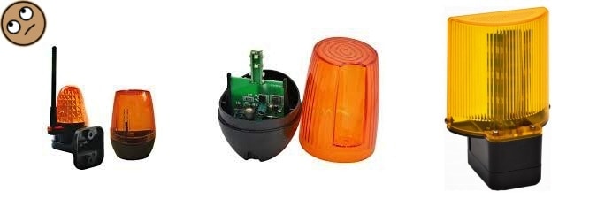
Flashing yellow lights are an essential part of sliding/swing gate and garage door automation systems, since they provide a clear indication that the system is installed and in operation. Thanks to LED technology, the total energy consumption is reduced by approximately 80% compared to traditional models with power-hungry incandescent light bulbs, while extending the lifetime of the device.
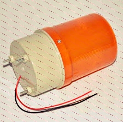
I always got a fascination with flashing warning lamps. I don’t know why, maybe simply because they don’t always have a burning eye but sometimes wake a little bit to raise an alert clearly. So, recently I decided to build one myself, and luckily, I got inspiration from the minimalistic design of a commercial product (see below).

The AC230V modular flashing gate light is in fact a simple device consisting of a system of circuits, that’s to say, a 555 timer based lamp flasher, a yellow LED plate, and a 12V SMPS module.
Certainly, this design idea has been around us for decades! So, during the construction of anew one we had to take a detour. Well, below you can see the schematic of my flashing yellow gate light (v1).
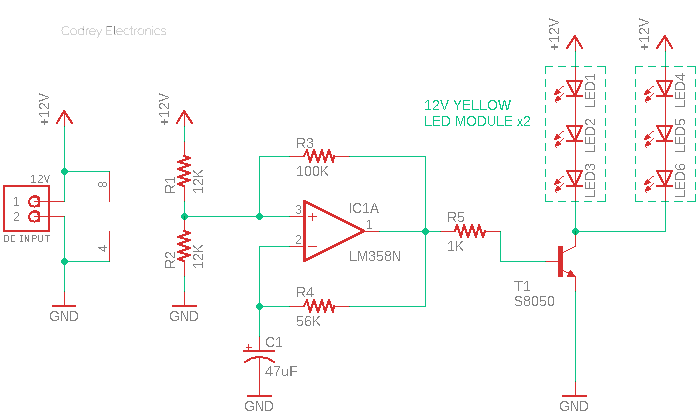
Get a look, this is the parts list:
- IC1: LM358
- T1: S8050
- R1-R2: 12K ¼ W
- R3: 100K ¼ W
- R4: 56K ¼ W
- R5: 1K ¼ W
- C1: 47uF/25V
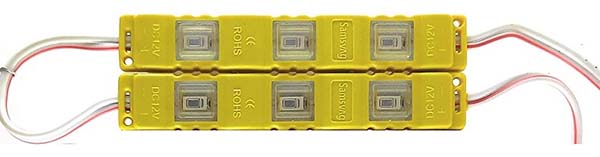
- LEDs: 12V/1.2W 5630 Yellow LED Injection Module x2
As visible in the diagram above, the electronics is extremely simple and can be powered directly by a compact 12V/5W SMPS module. The “HLK-5M12” will be a good pick here.

Hi-link’s HLK-5M12 is an encapsulated 12V/5W power supply module. The PCB-mountable isolated SMPS module can supply 12VDC from 100-240VAC and has a power rating of 5W, thus makes it perfect for small projects that need a stabilized 12VDC supply from mains (https://datasheet.lcsc.com/szlcsc/1912111437_HI-LINK-HLK-5M03_C209906.pdf).
Likewise, a pair of cheap 12V/1.2W 5630 yellow LED injection modules are recommended here to render a noticeable glow. As you can see, each LED module is composed by a sealed PVC plastic frame containing three chip LEDs in series, and they’re paralleled in this design.
These pretty cute LED modules can be directly connected to the recommended voltage source without using an external current limiting device (http://www.iled.com/class/INNOVAEditor/assets/4660-46645630RenkliModul.pdf).
Yeah, my flasher circuit is centered on the LM358 which consists of two independent, high gain, internally frequency compensated operational amplifiers designed specifically to operate from a single power supply over a wide range of voltages (https://www.onsemi.com/pdf/datasheet/lm358-d.pdf).
IC1A is a low-frequency oscillator (https://www.electronics-tutorials.ws/opamp/op-amp-multivibrator.html). I borrowed this idea from an LM358 application note but tweaked a bit for this project.

The frequency of oscillation is tuned mainly by C1 and R4, but is also subject to the threshold voltages the combination of R1, R2 and R3 generate when IC1A output is high or low.
And finally, the transistor T1 (http://media.nkcelectronics.com/datasheet/s8050.pdf) acts like a switch that turns on and off by the square wave signal and turns the LEDs on and off.
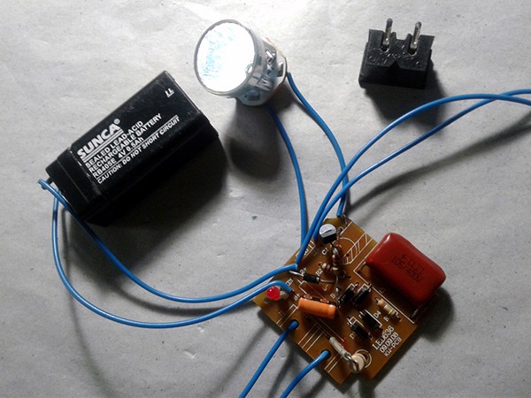
I decided to use a mini breadboard for my quick prototype as I still have a few ideas for betterment. Also, if the main design is built on a breadboard, it is easy to alter the basic design.
First, I tested my prototype with a 5mm yellow LED to make sure my idea was correct.

Thereafter I added the driver transistor there to complete my build and conducted the next test with a 12V/3W LED module. Oh well, it’s an interesting quick trial!

The following figure shows an artwork for the gate light enclosure. Needless to say, the entire circuitry (together with its power supply module) can be very easily installed inside the translucent enclosure (or an enclosure with a smoked yellow cap). Okay, get ready to 3D print it (Protection rating IP44).
Preparing this circuit to work together with an automatic gate opener is a bit laborious. You need to find the warning lamp terminals located on the gate controller device (See below. Thanks to https://www.youtube.com/watch?v=V2hLFYiDp9I).

Final Jots
- It seems that the flashing signal light for automatic gates available in 12V, 24V, and 230V versions. So, you may need to change the power supply section in your end-user model
- The gate lights are available in LED version with or without a built-in 433.92 MHz receiving antenna as well (time to introduce a new project – haha)
- This is a great note about automatic gates https://www.silvaconsultants.com/intro-to-automatic-gates
- Yes, we could make a warning light for gate opener systems with an Arduino/RPi, but frankly, that sounds like a bit of overkill
- I hope you’ll find this little post interesting and maybe of some inspiration to have some fun in your lab. Now let me warn you about the risks of the fatal high voltage involved with the circuit – be careful, it’s dangerous. Try it only if you know what you’re doing and at your own risk!


Awesome
Edward Simon: I’m glad to know that you feel that way. Thanks ⭐