Here’s a travel door sentry to safeguard your hotel room with a simple door sensor that will trip a warning alarm if anyone unlocks the door and intrudes. The battery-operated portable security device is very easy to use as it has a small leaf switch (two thin metal blades) that fit in the narrow gap between the door and doorframe, and a cord that you can loop around the door handle to keep it secure.

To set up, just hold the thin blades of the leaf switch together and simply insert it in between the door and doorframe, then loop the cord around the door handle. Once you armed the system, if anyone opens/breaks the door thereafter, detection by the leaf switch triggers an electronics circuitry and makes an intermittent blink and beep alert until it gets a reset from the possessor. In this article, we look at the development of its experimental design that you can try yourself!
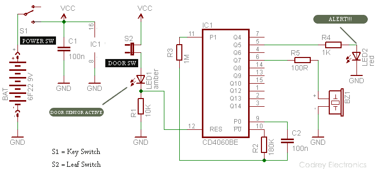
As you can see in the following circuit diagram, the design is based on a popular and inexpensive CMOS 14 Stage ripple-carry binary counter/divider and oscillator CD4060BE (IC1) with buffered inputs and outputs. The oscillator configuration allows the design of either RC or crystal oscillator circuits, and a negative transition on the clock will advance the counter to the next state. Also included on the chip is a reset function which places all outputs into the zero state and disables the oscillator. Datasheet – https://www.electroschematics.com/238/4060-datasheet.
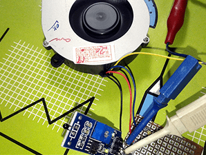
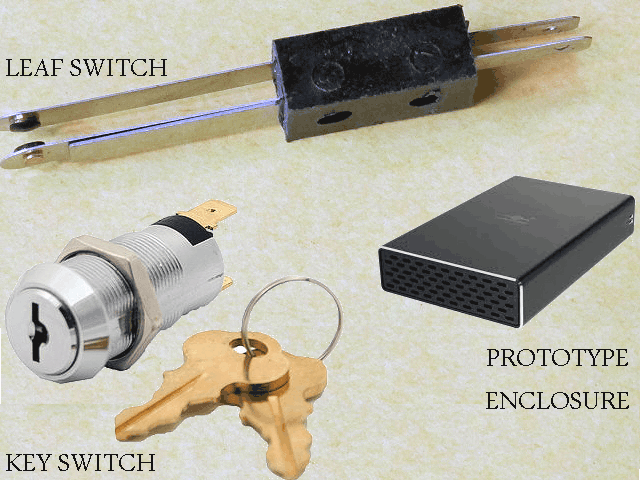
The power on/off switch (or Arm Switch) in the circuit (S1) is a small key switch, and the door sensor switch (S2) is a common leaf switch. A lightweight yet rigid prototype enclosure is required to complete the construction of the travel door sentry system. The leaf switch can be connected to the circuit through a 2-core low-voltage cable with a length of near 1 meter. And, one standard 6F22 9V battery is enough for powering the device up!
Two (Q5 & Q7) of the ten available outputs (Q4-Q14) of IC1 are used here to drive the alert indicator (LED2-red) and the active piezo-buzzer/sounder (BZ1). The reset terminal (pin 12) of IC1 is enabled by the door sensor switch (S2) in armed state and this condition is indicated by a feeble glow of the “sensor active” indicator (LED1-amber). Even though IC1’s outputs can give almost full supply voltage to drive low-current loads, try to drive the piezo-buzzer through a small-signal transistor, such BC547, if necessary. Note that IC1 is clocked by the RC oscillator made from pins 9, 10 and 11. Here, the values of the RC components R2 &C2 set the clock period.
This is just an experimental example, other timings can be achieved by changing the values of these RC components if you want to improve the overall design. For rough calculation of the clock frequency, try this formula: Fosc = 1/2.3 (R2x C2 ). The practical range of values for R2 is from 10 KΩ to 1 MΩ, while C2 can have any value from 100 pF upwards. However, take note the actual frequency is sometimes a little slower than you might expect because of the ‘stray’ capacitance between the tracks of the circuit board.
4060 Quick Calculation
As indicated above, here the frequency of the astable pulses can be calculated using the formula Fosc = 1/2.3 (R2x C2), in Hz (R in MΩ and C in uF).
If R2=180 KΩ and C2=100 nF, then Fosc = 1/ 2.3 x 0.18 x 0.1 = 24.15 Hz
& The Period of the pulses should be: 1/ (Fosc/2n)
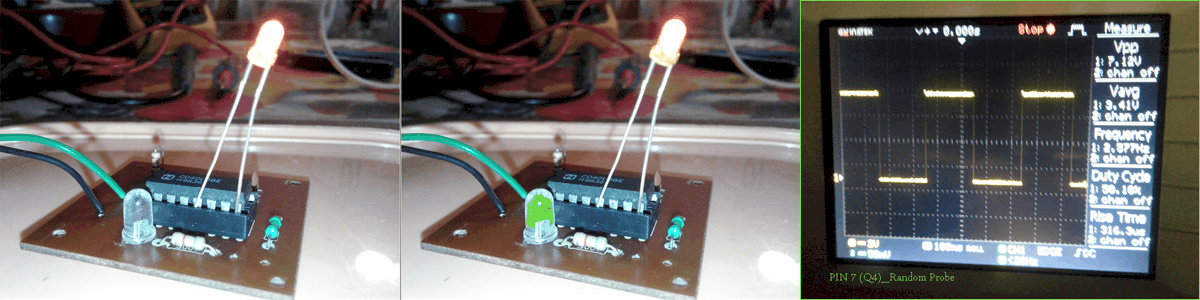
i.e. at Pin 7 (Q4), it’s 1/ (24.15/16) = 0.663 s
Note down, the pulses at Pin 7 (Q4) are divided by 24=16, and pulses at the final output Pin 3 (Q14) are divided by 214=16,384 compared with the initial astable frequency (Fosc)!
Addendum
This is an inspired design. You can see the root here: https://www.oddgifts.com/products/portable-door-alarm