Here’s one simple circuit idea of a 4-digit 7-segment light emitting diode display module which can be driven by many microprocessors and development boards. I have been using it with my Arduino microcontrollers since getting constructed. Apart from a 5V power supply, the module requires just three I/Os of the microcontroller, and only one header is needed to connect power and data lines to the module.
Key Components
- MC74HC595AD IC x2 (or the equivalent)
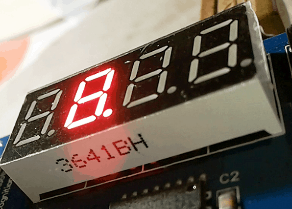
- FYQ-3641BH 4 digit 7-segment LED Display (or any other common-anode type) x1
- 100nF Capacitor x2
- 5-pin Header x1
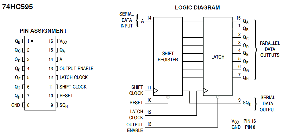
According to datasheet, the 74HC595 IC consists of an 8−bit shift register and an 8-bit D-type latch with 3-state parallel outputs. The IC directly interfaces with the SPI serial data port on today’s microcontrollers, accepts serial data and provides a serial output. The shift register also puts up parallel data to the 8−bit latch. The shift register and latch have independent clock inputs, too. The IC has operating Voltage Range of 2.0 to 6.0 V. See the pin assignment and logic diagram of 74HC595 shown below:
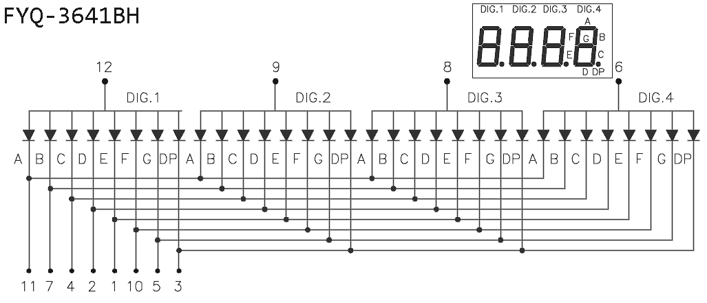
The FYQ-3641BH is a Chinese 4-digit 7-segment common-anode (red) LED Display. Here’s the internal diagram of the 12-pin LED display with pin out information:
Circuit Diagram
The 74HC595 IC uses the standard SPI interface, and thus accepts three serial control signals from the external microcontroller – Serial Data In, Serial Clock, and Latch Clock. Also see other relevant pin descriptions of 74HC595:
- Pin 14 of 74HC595 is the serial data input pin. Data on this pin is shifted into the 8−bit serial shift register
- Pin 11 is the shift register clock input pin. A low to high transition here causes the data at the serial input pin to be shifted into the 8-bit shift register
- Pin 12 is the storage latch clock input pin. A low to high transition here latches the shift register data
- Pins 15, 1, 2, 3, 4, 5, 6, 7 (QA-QH) are non-inverted, 3-state, latch output pins
- Pin 9 is the non-inverted serial data output pin. This is the output of the 8th stage of the 8-bit shift register (without tri-state capacity)
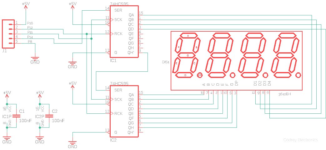
Making a 16-bit shift register by 74HC595 is extremely simple as it just need a 74HC595 daisy chain. In the circuit diagram you can see two 74HC595 ICs sharing common clock and latch pins but with the data output pin of the first shift register to the data input pin of the second one. In principle, the two daisy-chained shift registers operate like a single 16-bit register where the first device in the chain is the most significant byte (MSB), so it is the last to be filled while the second is the least significant byte (LSB), i.e. the first to be filled by the microcontroller’s serial data set.
Quick Test/Demo Code
Use this code to test the LED module with the help of an Arduino Uno. Look up the following table and continue:
| Arduino Uno I/O | LED Module Header (J1) |
|---|---|
| 5V | Pin 1 P16 |
| D4 | Pin 2 P12 |
| D7 | Pin 3 P11 |
| D8 | Pin 4 P14 |
| GND | Pin 5 P8 |
/*
 * DIY 4-Digit 7-Segment LED Display Module
 * Hardware: 74HC595x2 & 4-Digit 7-Segment LED Display (CA)x1
 * Demo Code Prepared in Arduino IDE 1.6.9
 * 74HC595 16-Bit Output Mode
 * Arduino Hardware: Arduino Uno (R3)
 * Author: T.K.Hareendran
 * Website: https://www.Codrey.com
 */

int LATCHDIOPin = 4; // Pin12 74HC595
int CLKDIOPin = 7;  // Pin11 74HC595
int DATADIOPin = 8; // Pin14 74HC595
unsigned int d;    // Data to be sent to the Shift Register
int dir = 0;       // Running Direction 1
char buf[12];      // GP Buffer

void setup() {

  pinMode(LATCHDIOPin, OUTPUT);
  pinMode(CLKDIOPin, OUTPUT);
  pinMode(DATADIOPin, OUTPUT);

  d = 1;
}

void loop() {

  delay(200);
  digitalWrite(LATCHDIOPin, LOW);
  shiftOut(DATADIOPin, CLKDIOPin, MSBFIRST, (0xff00 & d) >> 8);
  shiftOut(DATADIOPin, CLKDIOPin, MSBFIRST, 0x00ff & d);
  digitalWrite(LATCHDIOPin, HIGH);

  if (!dir) d<<=1; else d>>=1; // Shift

    if (d&0x8000) dir=1;      // Set direction
    if (d&0x0001) dir=0;
}
To get 16-bit output from the LED display, we should send 16 bits to the shift register, and it’s very important to send the bits from left to right (MSB first), alike:
shiftOut(dataPin, clockPin, MSBFIRST, highByte(numberToDisplay));
shiftOut(dataPin, clockPin, MSBFIRST, lowByte(numberToDisplay));
It’s essential to set the latch pin is to low before calling the shift operation, just to inform the device that the next bits should not be processed immediately. When the shiftOut() call returns, the latch pin signal is set to high to store the bits in the shift register. Have a look at various online tutorials to get more detailed information on how you can interact with shift registers (for instance, read this – https://www.arduino.cc/en/Tutorial/ShiftOut). Note that in my demo code, shift out function is used twice to output the 16 bit value through splitting into two pieces by bit shifting (shiftout operates on bytes only, thus can handle only 8 bits of data at one time).
Another suggested reading is https://weworkweplay.com/play/practical-guide-to-shift-registers/
A Brief Video
The prototype was wired on a piece of double-side prototyping board (not a photogenic one). The quick test video, however, is made with another repurposed hardware – an Arduino LED Shield – exactly rewired to my meet my design rules. Look on…
That’s all the hard work finished! Next, connect your assembled module up to any microcontroller of your choice and start having fun. There are hatful of example programs to get you going with wonderful codes for Arduino, PIC, RPi, etc. Well, if you have any comments/ suggestions (or letdowns), please get in touch.