Like the ducklings followed their mother around the pond, certain electronics hobbyists are still going along with pre-wired China modules. Certainly it’s not a good habit because by taking shortcuts (even for simple tasks) they’re not only killing their creativity but also dropping great chances for learning the art of electronic circuits (yes, it’s quite an art)!
Recently while cleaning my workbench, I unveiled a few LM331 ICs given to me by an online seller in India. As you may know, LM331 is a wonderful chip for voltage-to-frequency (V-F) conversion, and a superb component to start fiddling with analog electronics. Luckily, we can also use the LM331 to build light intensity-to-frequency converter circuits. This article describes a lucid way to build a Light-to-Frequency (L-F) Converter Module based on LM331. The circuit is in fact an adapted version of one application idea found in the official datasheet released by Texas Instruments (www.ti.com).
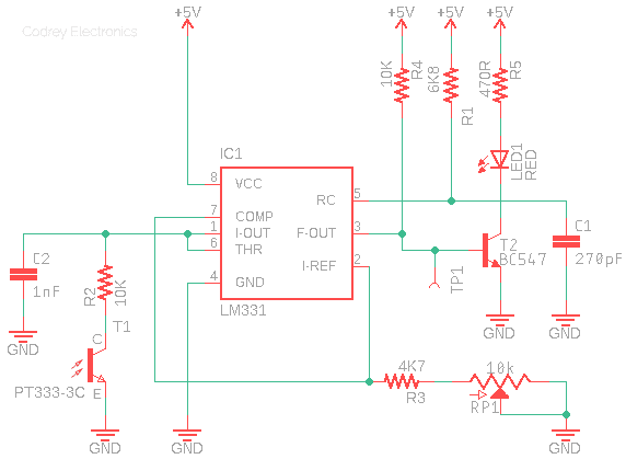
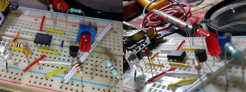
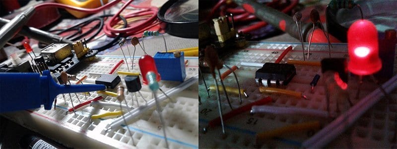
In the basic light to frequency converter circuit shown above, one PT333-3C (5mm silicon NPN phototransistor from Everlight) is used as the light receiver (T1). Anyway, you can try other compatible phototransistors (for example, the SFH300 from Siemens) here. RC components R1 (6.8K) and C1 (270pF) set the frequency of IC1 (LM331/KA331). Note that the output frequency (duty cycle, as well) changes as the input light intensity changes, and the waveform driving the visual indicator (LED1) can be taken from the point TP1 (see the scope trace). Resistor R4 (2K2-10K) is a pull-up resistor because the output (pin 3) of IC1 is an open-collector terminal. Resistor R5 (470R-1K) sets the drive current for the red indicator (LED1) which lights up entirely if the light receiver (T1) gets zero light.
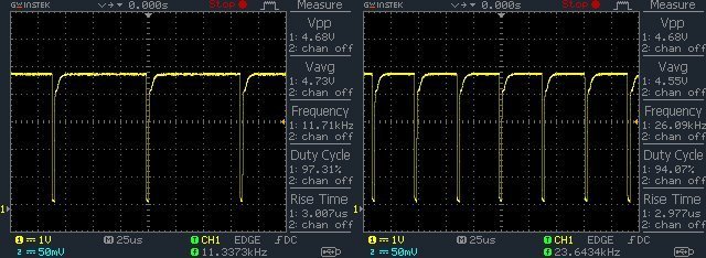
As stated initially, the idea is pretty much cribbed from the datasheet. However, in my design of this light controlled variable frequency oscillator, I slowed the frequency down so we can see the visual blink i.e. eye blink of the LED, impelled by IC1 through transistor T2 (BC547). Calibration of the converter is done with the 10K multiturn trimpot (RP1) preferably a standard 10-turns type, but would require access to a frequency counter/oscilloscope for serious settings.
LM331 is much simpler to interface and very linear. It’s available in an 8-pin DIP package and works with a single supply voltage from DC 4V-40V (my design is tailored for 5V). The simple hobby project is useful at least to the degree that we can read an input signal by displaying the output frequency on a frequency counter/oscilloscope if we scale the input signal range and output frequency range accordingly.
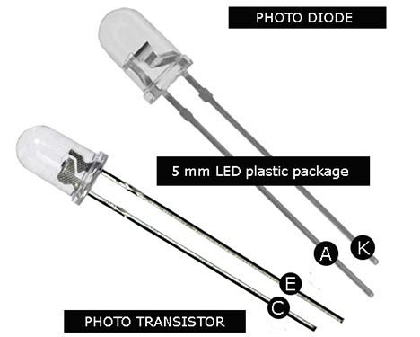
Today we can find cheap phototransistors and photodiodes both in 5mm LED plastic package. Both the phototransistor and photodiode work on the background of inner photoelectric effect. In principle, a phototransistor uses normal transistor but with two terminals namely emitter (E) and collector (C), whereas in a photodiode ordinary PN junction diode which has anode (A) and cathode (K) terminals is used. Quite often it’s very difficult to key out the former from the later. So, note that usually the longer of the two pins indicates the phototransistor’s emitter (E) terminal, while in a photodiode the shorter pin denotes its cathode (K).
The LM331 is ideally suited for use in simple inexpensive circuits good for analog-to-digital conversion and many other tasks. The output when used as a voltage-to-frequency (or light-to-frequency) converter is like a pulse train at a frequency precisely proportional to the voltage (or signal) at the input. Further, its input (and output) can be easily channeled with the help of a standard opto-isolator to provide perfect galvanic isolation. I may develop distinct ideas and write more on this later, but for now I can at least present experimental proof that it works. Meanwhile, refer to the LM331 datasheet for more fascinating circuit ideas.
Quick Datasheets
- PT333-3C: 5mm water-clear phototransistor http://www.everlight.com/file/ProductFile/PT333-3C.pdf
- SFH300: 5mm water-clear phototransistor http://www.mantech.co.za/datasheets/products/SFH300-XXX.pdf
- LM331 IC: http://www.ti.com/lit/ds/symlink/lm231.pdf
- SFH203: 5mm water-clear silicon PIN photodiode https://dammedia.osram.info/media/resource/hires/osram-dam-5488331/SFH%20203%20FA_EN.pdf
- EAPDLP05RDDA1: 5mm water-clear silicon PIN photodiode https://www.mouser.com/ds/2/143/EAPDLP05RDDA1-737296.pdf