 The quick way to build an electromagnet based project is to buy one lifting electromagnet with enough lifting and holding power to fulfill the design requirements. Such compact and powerful lifting electromagnets in various shapes are now available from almost all online electronics component vendors and storefronts.
What are lifting electromagnets?
The common circular lifting magnet is an encapsulated DC electromagnet usually available with easy to use mounting accessories. Usually large diameter lifting electro magnets transport steel scrap in scrap processing yard/foundries and they can handle tones of scrape continuously throughout the day. However, you can use the smaller versions to build your own electro-mechanical models such as mini magnetic cranes, superb magnetic levitators, etc.
How to select the right electromagnet?
Naturally, once you know the available voltage and current, you can pick a suitable lifting electromagnet that matches perfectly with the design requirements. But you need to know about its strength/force which is usually marked as a number with a suffix “N”. For example, see the specifications of a popular Chinese lifting electromagnet sold by eBay.
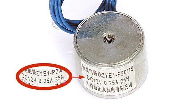
Here, the label denotes that it’s a DC12V, 250mA, 25N lifting electromagnet. Needless to say, its operating voltage is 12V and current requirement is 250mA (0.25A), so it has a coil resistance close to 48Ω. That’s okay but what does the “25N” means?
The “25N” simply mentions 25 Newton! 1 Newton in earth gravity is the equivalent weight of 1/9.80665 kg on earth. This is derived using Newton’s second law f=ma and assuming earth gravity of 9.80665 m/s2. 1 N (Earth) = 0.101971621297793 kg. Converting 25N to kg, you get 25N x 0.102 = 2.55 kg, and that means the electromagnet can lift 2.55 kg on earth. Suppose you wanted to lift a load of 80kg on earth, then opt for an 800N lifting electromagnet. Did you get the math?
Build your own lifting electromagnet!
You can, ofcourse, make your own lifting electromagnet from scrap by winding lengths of suitable magnet wire (enameled copper wire) around a cylindrical core. Routing an electrical current through the coil results in a magnetic field that exerts force on nearby ferromagnetic objects, such as pieces of iron or steel. Even so, I would like to guide you through a less-popular trickery that help you to make one powerful lifting AC/DC electromagnet by modifying the existing AC electromagnet of a cheap (and common) aquarium air pump.
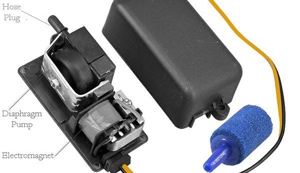
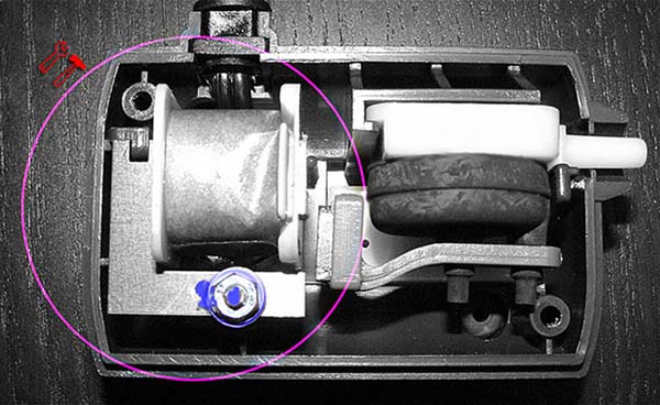
The most commonly used external aquarium air pump is the diaphragm pump delivers air in pulses as an electromagnet opens and closes the diaphragm, forcing water to make bubbles. Aquarium air/oxygen Pump helps pumps oxygen into the aquarium. Its installation is easy as you only need to fasten one end of a silicon hose to the pump and the other end of the hose to the air stone and place the air stone inside the aquarium. Note that you only need the electromagnet of the aquarium air pump so detach it from the enclosure, and keep the remaining parts intact so that you can build some projects with them in future.
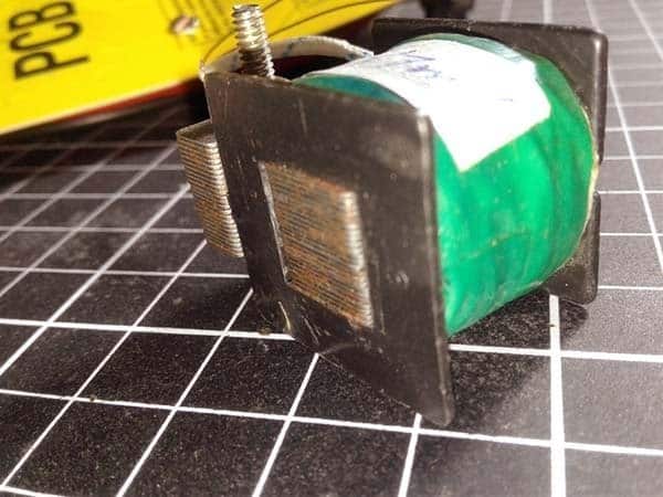
Now to the hard part! Remove the stacked core of the electromagnet at first, wind off the coil, and then wind a new coil on that bobbin with 26SWG (or 27SWG) magnet wire. Don’t worry about the number of turns but the wire should cover the bobbin entirely. After you have completed the winding job, put some electrical tape around it so you do not scratch the magnet wire and short it out, and finally insert the stacked core back into the bobbin carefully. Yes, you did it!
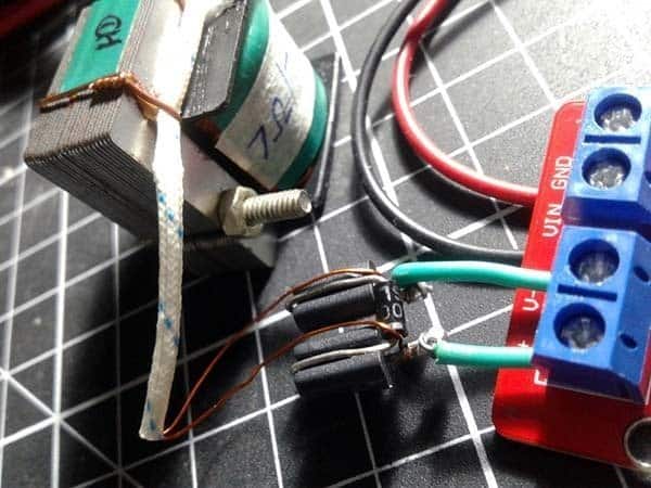
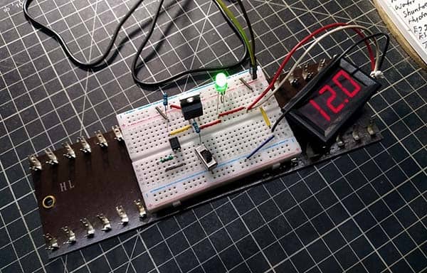
Below you can see my ‘homemade’ lifting electromagnet. It’s a coil with dc resistance of 7Ω and an impedance around 7mH (my LCR meter can’t fool me, I still believe). Surprisingly it starts getting magnetized from DC voltage as low as 1V, besides it possesses terrific lifting (and holding) power if the applied voltage goes up in 6-12V scale.
See my homemade “~20N” lifting electromagnet’s voltage & current relationship chart below.
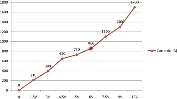
I’d prefer the middle level 6VDC operation rather than the top level 12VDC as the latter will heat up the electromagnet much faster. Actually such a high voltage, high current, drive is superfluous here because the electromagnet seems so powerful even with a 6V/860mA drive (it even kept a firm hold on my heavy nose pliers).
Electronic switch/driver for lifting electromagnets
When it becomes necessary to switch or control a lifting electromagnet by an external device or microcontroller circuit, you should need an appropriate circuitry based on a BJT or Power MOSFET. This circuit diagram given below demonstrates the simplest form of an electromagnet driver circuitry and may be used to actuate most low-power lifting electromagnets.
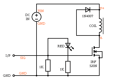
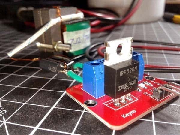
The circuit, actually a readymade IRF520N Power MOSFET module from Keyes, requires an input voltage (VIN) to actuate the electromagnet as well as a control signal (SIG) input (from a controller or timing device), which switches the power MOSFET that in turn permits the drive current to energize the electromagnet. The additional diode placed parallel to the electromagnet is to protect the power MOSFET from inductive voltage spike that occurs as the electromagnet de-energizes.
According to its datasheet, RDS(on) of IRF520N Power MOSFET is 0.27Ω (VGS = 10 V). Since the electromagnet (made by me) draws around 900mA at 6VDC (its dc resistance is 7Ω), rough calculation finds that the 270mΩ MOSFET would dissipate around 219mW here. The TO-220 package would get hot in free air, but should be able to handle it. It’s observed that the RDS(on) at 5V VGS is about 0.5Ω which results in 405mW of power dissipation. Again small enough so that a fat heatsink is not very crucial for the power MOSFET. In actual fact, RDS(on) would matter only in case of huge currents, otherwise it doesn’t matter in most cases.
Utilizing PWM Drive
Pulse width modulation (PWM) drive will be a good option for modulating the coil current of the lifting electromagnet. However, it’s not easy in real world because of a few issues to be considered seriously. By the way, I’m working on a universal PWM driver circuit for lifting electromagnets but now it’s in infancy. My real intention is to build two versions – the first one will be a voltage control module, and the second will be a current control one, both with a pick and hold power control mode. I discuss nothing more about the PWM drive methods at this moment as there’re a number of subtle things that should probably be covered. Hopefully I can share the full-fledged post within a couple of weeks. Any hints would be much appreciated!


So? No follow up on this? was getting really interesting. Would had liked to read about those issues with PWM, as it’s the same I’m after, though.
Eduardo: Thanks for the reminder. I still need to test the concept more extensively,, but from a technical standpoint it is working very well at the moment. So probably you can see the sequel here in next month. And, I am glad you found the post useful!