Nowadays solid state relays (SSRs) can be found in almost every online electronics store, and SSRs are certainly the most ‘silent’ relays available. However, I would like to point out at first that SSRs are not suitable for all projects, and you must use them with extreme care. At all times make sure that what you picked out is a right SSR for your project, and you know what you are doing!
What is a Solid State Relay?
In fact, an SSR is not very different in operation from a common electromagnetic relay (EMR) that have movable switch contacts. However, the SSR have no such movable contacts but employs a semiconductor switching element. Besides the SSR employs a photo-coupler to isolate its input and output segments. Since SSRs can provide high-speed, high-frequency switching operations with zero operation noise, they are ideal for a broad range of applications that might not possible easily with EMRs.
G3MB Series SSRs from Omron
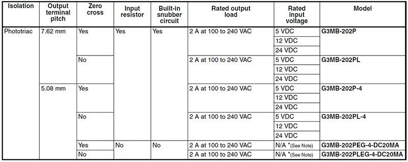
Perhaps, one quite popular SSR crawling along the hobby electronics world is the low cost, sub miniature, PCB mounting, G3MB series SSR from Omron (www.omron.com). You can buy it as independent SSRs or a prewired SSR boards/modules usually coming from China. Note that a large number of such Chinese SSR modules are built around the G3MB-202P SSR from Omron.
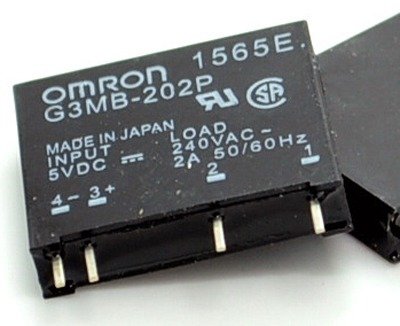
The Omron G3MB-202P is a 5V DC input, 240V AC (2A) output SSR, consists of a phototriac coupler and a triac. It also has a snubber circuit and zero-cross function. The phototriac coupler transfers the input signal and insulates inputs and outputs as well. The snubber circuit is a little circuit consisting of a resistor and capacitor, which prevents faulty ignition from occurring in the SSR triac by suppressing a sudden rise in the voltage applied to the triac, while the zero-cross circuit is a circuit which begins operation with the AC load voltage at close to zero-phase. Rather unsurprisingly, the G3MB-202P is a model with inbuilt input resistor (440Ω ±20% for 5V).
Naturally, prime focus of this article is on G3MB-202P solid state relay because it’s much popular, and probably the best-loved SSR as witnessed. Following section describes an extremely simple idea to build your own microcontroller-compatible G3MB-202P SSR module.
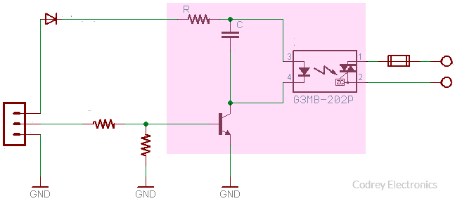
Build Your Own G3MB-202P SSR Module
A prewired SSR module not only reduces your project prototyping time but also protects the SSR from accidental damages caused likely by incorrect handling. Let’s take a look now at the circuit diagram.
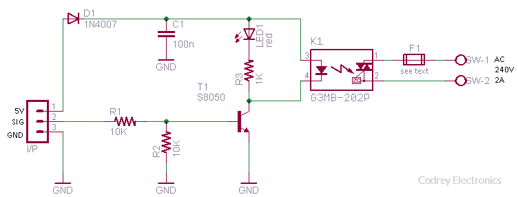
Now you’ve a G3MB-202P general purpose 2A/240VAC solid state relay module. In the above schematic diagram, the 1N4007 diode (D1) is added deliberately to protect the input circuit of the G3MB-202P SSR (K1) because its input circuitry does not incorporate a circuit to protect it from being damaged due to a reversed polarity input connection. The S8050 driver transistor (T1) is wired to turn-on the SSR when a logic-high (H) level signal is inputted to the SIG pin of the input header (I/P). In order to run the module you should also input 5VDC through the 5V pin of the input header. Typical operating current demanded by the module is about 10mA at 5VDC. The red LED (LED1) is the relay status indicator which lights up when the relay is in on state. The switch contacts (SW-1 & SW-2) can be used to switch AC240V loads up to 2A. The fuse (F1) is an optional output protection component but it’s highly recommended. You can use a fast 2A/240V (or slightly above) resistance fuse – preferably one Littlefuse™ – there (see next figure).
Warning! Circuits at live potential should only be constructed/tested/used by experienced personnel.
SSR Module Usage Hints
As stated previously, SSRs too have many application limitations, hence always use them in your projects with great care. Coming to the SSR module presented here, do remember that the rated input voltage is 4 to 6VDC (5V typical), and the rated output load is 2A at 100 to 240VAC. The maximum ‘output on voltage drop’ is around 1.6V(RMS).
So make sure that you’re running your SSR module within the rated limits. Here, the maximum output load current was rated assuming a single resistive load is connected at the output. To allow for an adequate safety margin, the advised values are 20% – 30% lower than the rated values. Furthermore, your G3MB-202P SSR module is ofcourse a general purpose one but you can’t use it in phase control circuits (it’s because of the inbuilt zero-cross circuit). If you’re looking for an SSR module particularly good for phase control applications, then replace the G3MB-202P SSR in your module with a G3MB-202PL SSR (no more changes needed).
There’re many more significant things to talk about but space restraints forced me to shrink that abruptly. So, here’s a bulleted list:
- Don’t use your SSR module for switching electrical loads powered by a square wave inverter. Your SSR module uses a triac which turns off the element only when the circuit current is 0A in the output element. If the load current waveform is rectangular, it will result in a SSR reset error
- Keep note, even when there is no input signal to the SSR there is a feeble leakage current from the SSR output load
- Since large inrush current (up to 15 times higher than the rated current value) might flow through incandescent lamps, halogen lamps, etc, ensure that the peak value of inrush current does not exceed ½ of the inrush current resistance of the SSR
Noise across the input points of the SSR module may result in malfunction. However, a resistor-capacitor (RC) combination can absorb pulse noise effectively (see the example given below)
Here, the RC values must be calculated carefully. The value of R should not be too high because the supply voltage will not be able to cater the required operating voltage value with such a higher value resistor. Likewise, the larger the value of C is, the longer the release time will be, due to the discharge time taken by C. Recommended value of R is 20 Ω -100Ω and C is 10nF-1uF, to reduce noise generated from high-frequency equipments effectively.
Chinese G3MB-202P SSR Modules
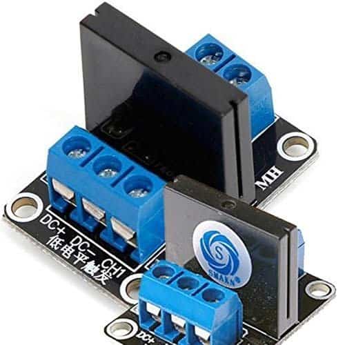
Commonly available Chinese G3MB-202P SSR modules follow the same circuit introduced here to help you build your own SSR module. However, there’re two versions i.e. one with active-high (H) switch input, and the other with active-low (L) switch input. So look twice while buying Chinese SSR modules. The active-high model usually has a J3Y (S8050) SMD driver transistor while the active-low model is based on 2TY (S8550) SMD transistor. That’s the main difference between them.
Confusing Seller Description
No surprise, once again our online sellers proved that device specifications can be presented in ways that are misleading! See one seller’s item description below.
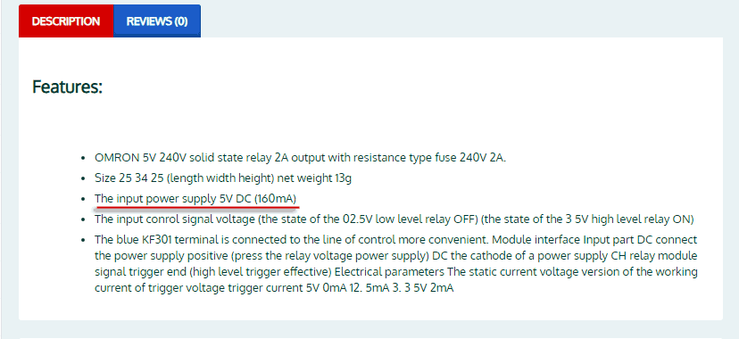
I don’t know why 160mA at 5V input supply is needed for the G3MB-202P SSR module. What I can see is a value that never goes above 10mA at 5VDC (FC-85 Module). I am guessing that the 160mA denotes the demanded value of an 8-channel SSR module (8x20mA), or the like!
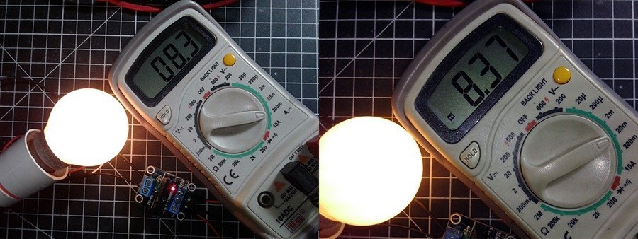
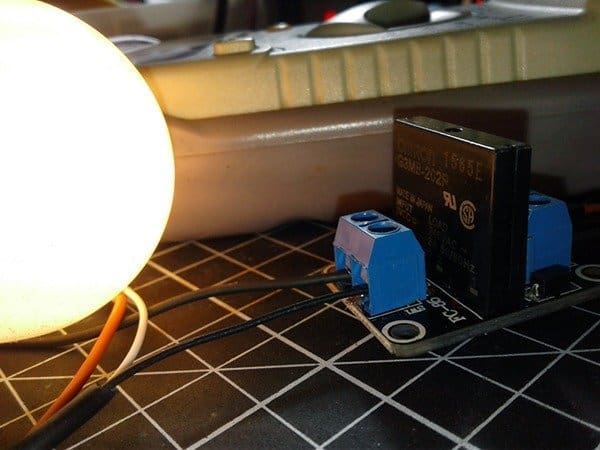
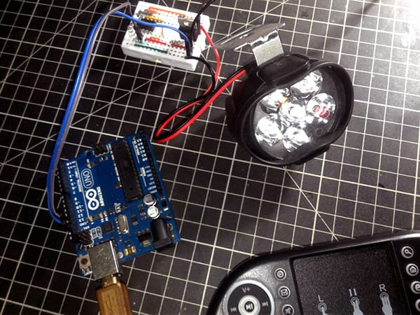
Lab Snaps
That’s all for now. Learn, Build, Enjoy…!
Here you can find more about the “Littelfuse” described in this article:
https://www.littelfuse.com/products/fuses/military-high-reliability-fuses/high-reliability-and-military-fuses/253.aspx
Is it ok if we don’t place any resistor to the input of the ssr?
Rahmat: It depends on the type of SSR as every photo-coupled device will need some sort of current-limiting component.
The G3MB-202P SSR has a built-in resistor, so you may use it without an external resistor. However, no harm will result from adding an “calculated” external resistor when you’re unsure.
BTW, always fully disclose your project details/schematic when discussing your application. If you are looking for a more practical suggestion than a “Google Reply” it is the right approach. Hope you understand!
I’m not in love with the layout of the 1 channel boards. The fuse comes from the AC side and terminates right next to the low voltage side, with just a few mm separation. Not enough in my opinion. The 2 and 4 channel boards have better isolation.
Gregory: Good observation (often overlooked by many). Thanks!
As you can see, this is common on cheaper Chinese modules. So, only consider them as “Arduino Hello World” SSR modules 😜
BTW, I often use multichannel Grove SSR modules from Seeed Studio (https://www.electronicscomp.com/image/cache/catalog/seeedstudio-grove-4-channel-solid-state-relay-2-800×800.jpg). A little better in every sense!
can this relay works with 3.3 V ? B/c i am designing it with esp32.
Ayush Raj: Yes, the shown setup will also work with 3V (or 3.3V) signal (SIG) input. Otherwise, reduce the value of the 10K resistor (R1) to 4.7K or lower.