Here’s the simple circuit of an ultra-sensitive knock sensor for microcontroller-based electronics projects. It’s in fact a piezo knock sensor monitor based on a single transistor, and designed carefully to work with 5V (or 3.3V) regulated dc power supply. The ‘sensor-head’ in this design is an ordinary 35mm piezo-ceramic disc that can be easily reachable by electronic hobbyists, engineers and designers.
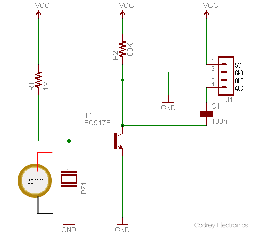
See that the one and only active component in the given circuit is a BC547B transistor (T1). The 35mm piezo-ceramic disc (PZ1) is connected directly across its base and emitter leads. The 1MΩ resistor (R1) is responsible for the overall sensitivity of the knock sensor i.e. raising its resistance value will increase the detection sensitivity and a lower resistance value will decrease the detection sensitivity. Anyway do not use a value higher than 4.7MΩ or lower than 1MΩ for R1.
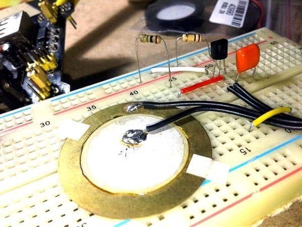
The 4-pin header (J1) has 5V, GND, OUT, and ACC connection terminals to interface the knock sensor easily with an external microcontroller circuit. The piezo-ceramic disc (the sensor-head) must be glued to a solid base with its brass-part faces that surface. Below you can see a casual snap of my breadboard prototype.
Here, the OUT is the default output connection but the optional ACC (AC-Coupled) output allows you to ‘listen’ the knock with the help of an external audio amplifier or an audio-shield. Usually if you connect a pre-wired Chinese knock sensor module to an audio amplifier circuit, you’ll get only a ‘tinny’ sound, but it’s sure that this knock sensor circuit will give you a ‘bass-rich’ audio output if connected with a good audio amplifier.
If you want to use this knock sensor with Arduino, it’s very easy to prepare an ‘analog read’ sketch to read the output (OUT) of the knock sensor. For example, the following ‘analog-to-digital conversion’ sketch is to read the output using analog Read() command, encoding the voltage range from 0 to 5 volts to a numerical value from 0 to 1023. By simply connecting 5V to 5V, GND to GND and OUT terminal of knock sensor to Arduino’s Analog input pin A0, you can make the simple test setup. After the hookup is over upload the following Arduino code.
#define KNOCK 0 // Knock Sensor OUT to A0
byte val = 0; // Initializing the variable for the knock value
void setup()
{
Serial.begin(9600); // Initializing the serial port at 9600 baud
}
void loop()
{
val = analogRead(KNOCK); // Read the knock value
Serial.println(val, DEC); // Print the voltage to the terminal
}
If you want another sketch that helps you to serial print the knock sensor’s output as ‘real’ voltages, then try this one.
const int KNOCK_OUT = A0; //Knock Sensor OUT to A0
void setup()
{
Serial.begin(9600); //Initializing the serial port at 9600 baud
}
void loop()
{
// Read ADC value in, and convert it to a Voltage
int knockADC = analogRead(KNOCK_OUT);
float knockV = knockADC / 1023.0 * 5.0;
Serial.println(knockV); // Print the voltage to Serial Monitor
}
You can certainly make your own knock-controlled devices (knock-triggered alarms, lights, etc) with the help of crest-detection sketches similar to the one shown next. Such codes simply monitor the knock level and gives a digital output through one I/O of Arduino only when the knock level goes above a threshold level. The sketch itself is not pretty – sure there will be readers out there picking holes in it!
#define KNOCK1 0 // Knock Sensor OUT to A0
#define LED 13 // Digital Output Pin
#define THRESHOLD 100 // Threshold Level
byte val = 0; // Initializing the variable for the output value
void setup()
{
pinMode(LED,OUTPUT);
Serial.begin(9600); // Initializing the serial port at 9600 baud
}
void loop()
{
val = analogRead(KNOCK1); // Read the knock input
Serial.println(val); // Print the output to the terminal
if(val > THRESHOLD) { digitalWrite (LED,HIGH); delay(1000); digitalWrite(LED,LOW); }
else if(val >0) { digitalWrite (LED,LOW); }

}
Take note, although the circuit is functional in full, the Arduino sample sketches given here cannot hope to fulfill every requirements. For this reason be prepared to do some experimenting with the sketches to get the results you want. I’m sure, there are many other ways to do that!
Arduino I/O Limits
When you need to read in a voltage on an Arduino Uno’s I/O pin, make sure it’s between 0V and 5V as the ATmega328 microcontroller chip on the board can handle voltages between 0V to 5V, and the absolute maximum rating is -0.5V to VCC+0.5V only. As far as I know, if your input signal is digital you can clip an input outside these limits by adding a single resistor in series with the particular I/O pin because the ATmega328 I/Os have internal clamping diodes (https://scienceprog.com/using-current-limiting-resistors-on-avr-io-pins/).
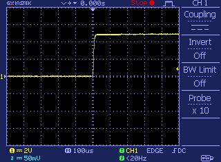
Luckily in this case the maximum output from the knock sensor circuit is within the allowed scale even when there’s a very hard knock (see oscillogram). So I think it’s not very necessary to scale down it in most instances (I welcome your suggestions). Anyway you’re free to add a bit of protection using an appropriate transient voltage suppressor (TVS) or the like at the analog input of Arduino Uno.
Just to recap, piezo-ceramic discs come in handy when you need to sense knock or vibration. A typical knock sensor is a piezoelectric sensor that contains a piezo-ceramic disc (piezoelectric sensing crystal) and a resistor. The piezo disc generates a small amount of voltage when excited. The do it yourself knock sensor circuit introduced here takes advantage of the unique piezoelectric property however with a little refinement. That’s all for now!