I finally got around to testing this concept – adding a crosswalk button to the previously published Arduino Traffic Lights project
I must admit, I was surprised to find a compact traffic light controller module in my junk box. In fact, I almost forgot about it. If my memory is good, it’s a gift from a friend abroad a few years ago. Anyway, that module (https://www.trafficlights.com/controllers/n3-ryg-light-controller/) suddenly reminded me of the promised sequel to the aforesaid article.
Okay, the project at this time is controlling the pedestrian signals (https://en.wikipedia.org/wiki/Pedestrian_crossing) with an Arduino, so it will automatically step through the states of solid don’t walk (red), solid walk (green), and flashing alert (green) if the crosswalk button is depressed by a pedestrian. In addition, it controls the auto traffic lights – solid red (stop), solid yellow (get ready), and solid green (go).
I have tried a number of different Arduino Sketches for this project and the one that works well (especially in my quick tests) is given below. As you can see, the code on the Arduino Uno end is pretty simple and self-explanatory!
int autoRed = 13;
int autoYellow = 12;
int autoGreen = 11;
int pedRed = 10;
int pedGreen = 9;
int button = 8;
int crossTime = 5000;
unsigned long changeTime;
void setup() {
  pinMode(autoRed, OUTPUT);
  pinMode(autoYellow, OUTPUT);
  pinMode(autoGreen, OUTPUT);
  pinMode(pedRed, OUTPUT);
  pinMode(pedGreen, OUTPUT);
  pinMode(button, INPUT_PULLUP);
  digitalWrite(autoGreen, HIGH);
  digitalWrite(pedRed, HIGH);
}
void loop() {
  int state = digitalRead(button);
  if (state == LOW && (millis() - changeTime) > 5000) {
    changeLights();
  }
}
void changeLights() {
  digitalWrite(autoGreen, LOW);
  digitalWrite(autoYellow, HIGH);
  delay(2000);
  digitalWrite(autoYellow, LOW);
  digitalWrite(autoRed, HIGH);
  delay(1000);
  digitalWrite(pedRed, LOW);
  digitalWrite(pedGreen, HIGH);
  delay(crossTime);
  for (int x = 0; x < 10; x++) {
    digitalWrite(pedGreen, HIGH);
    delay(250);
    digitalWrite(pedGreen, LOW);
    delay(250);
  }
  digitalWrite(pedRed, HIGH);
  delay(500);
  digitalWrite(autoYellow, HIGH);
  digitalWrite(autoRed, LOW);
  delay(1000);
  digitalWrite(autoGreen, HIGH);
  digitalWrite(autoYellow, LOW);
  changeTime = millis();
}
It’s that simple. My hardware setup diagram looks like this:
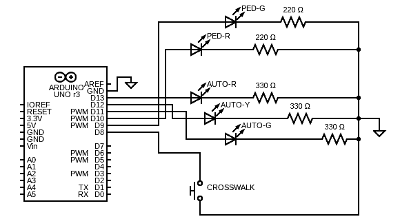
I used a couple of ready-made RYG Traffic Light LED Modules to test my idea. And, in the usual manner, the Arduino Uno board is powered by a healthy 9V battery. To practice this system, I rigged up a basic model as shown below.
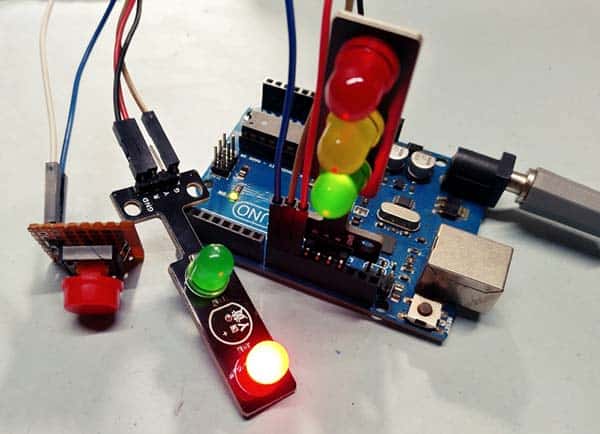
Needless to say, this is a basic stop/go crosswalk signal light without a countdown timer or accessibility features. The pedestrian sign is handled by two LEDs – the red one powers the “don’t walk” part of the sign, and the green one powers the “walk” part.
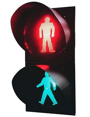
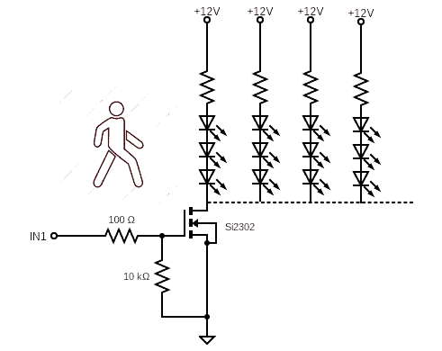
By all odds, you can make a bombastic pedestrian sign with the help of a bunch of red and green LEDs similar to the one shown below. Follow the appropriate calculations. I won’t get into the actual construction scheme at this time.
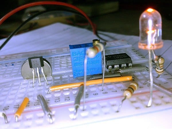
Anyway, in a bit more detail, this elaboration obviously calls for a couple of N-channel Logic-Level Power MOSFETs to drive the LED clusters (see below). I originally used a pair of Si2302DS Power MOSFETs (https://www.vishay.com/docs/70628/70628.pdf) for the agile tests whilst utilizing an independent 12V DC power supply for the homemade stop (red) and walk (green) pedestrian signs.
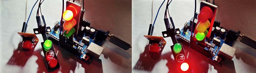
Note that, at intersections with live traffic signals, the crosswalk button functions as a human detector, alerting the traffic control system to the presence of a pedestrian and requesting a walk signal as soon as possible.
In this setup, you have to push the crosswalk button to cross the road, otherwise, the system doesn’t know there’s a pedestrian waiting and will remain in its default state without ever displaying a walk signal. Needless to say, the display cycles do not change in a flash because the system always needs to complete its existing cycle.

Finally, my next idea is to include simplistic remote-control support so pedestrians can use a wire-free control button to start the crosswalk cycle. You may be curious about what’s inside the remote-controlled pedestrian sign. What I’ve is the wireless control button unit which goes inside a project case that might be attached to a sidelong traffic pole. I’m afraid that I’ll need a bit more time to share the project details. So, till then, Happy Trails!