Want an inexpensive locker security switch? Look no further – build this little but versatile project. All components for this project should be readily available at any reasonable electronics components supplier, and the construction of the circuit should present zero problems. Well, pass some time with this stealer-unfriendly theme!
The locker security switch introduced here is a great way to deter sneaky stinkers and alert you to anyone trying to get their grubby mitts on your money. It can keep guard and sound an alarm even while you’re not around. Moreover, you can use this simple idea on anything that closes – a window, a door, a cupboard – so get creative with this locker security switch!
Schematic diagram
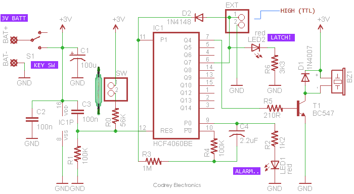
As depicted in the above schematic, the design is centered on a single IC – the HCF4060 (IC1), which is tailored to monitor a normally-closed switch input port (SW) perpetually, and readied to drive one active piezo buzzer (BZ1) together with a pair of 3mm red LEDs (LED1 and LED2) while alarmed. The circuit, operates on a 3VDC supply (1.5V AA/AAA dry cell x2), also has a small key-operated on/off switch (S1) to arm/disarm the security switch/alarm. Moreover, the circuit provides a TTL level logic signal output through its output port (EXT) that enables you to drive a remote security alarm device – wired or wireless.
A bit of working description
This design closely follows the typical application circuit of HCF4060 which consists of an oscillator section and 14 ripple carry binary counter stages. The oscillator configuration allows the design of simple RC oscillator circuits, and here components R4-C4 is employed there. The counters are advanced one count on the negative transition of each clock pulse, and the counters are reset to the zero state by a logical “1” at the reset input (pin 12) independent of clock.
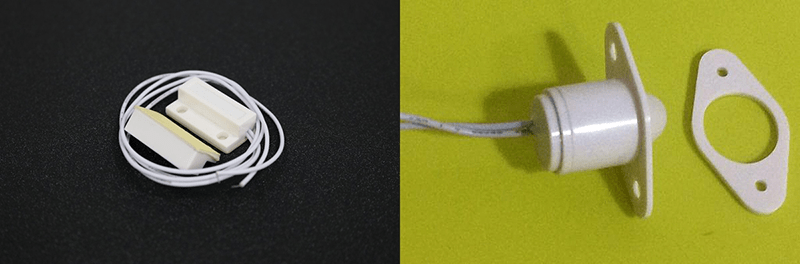
The ‘hidden’ key lock switch (S1) routes the supply voltage from the 3V battery pack. In standby state nothing befalls in the circuit because the switch input (reset pin) is pulled to ‘high’ by the associated door switch/sensor of the locker. A normally-open type reed switch and a strong bar magnet will work as the locker door switch/sensor. However, you can also employ a common magnetic door switch or a small recessed door switch (look below). The BC547 Transistor (T1) acts as a switch and ensures adequate drive current is provided to the piezo-buzzer (BZ1). Diode D1 (1N4007) acts as a flyback diode which protects the transistor from potential voltage spikes induced while using a cheapo piezo buzzer.
Opening of the locker door will disable the reset mechanism of IC1 because its reset pin is then grounded by the 100K resistor (R1). Consequently, the first red indicator (LED1) starts flashing, and after a few flashes, the sounder (BZ1) starts beeping for a couple of moments. Within this time period, closing the locker door will hush up the alert. Note that only the possessor can flip the key-locked hidden switch (S1) to go along with an opened locker door.
If the locker door remains open even after the aforesaid time period, the alarm function comes to a halt – right time for the second red indicator (LED2) to awake. At the same instant, a ‘reset-able’ latched output is handed over through the external 2-pin drive connector (EXT). The latched logic-high (TTL Level) signal can then be used to trigger any wired or wireless remote alert devices while keeping the trigger a secret. In order to establish a wireless link, opt for your fave wireless module – Bluetooth, Wi-Fi, or RF for instance. By the way, I’ve got one idea in mind for this – a topic for another post!
Nevertheless, you don’t need to follow the core design strictly, it’s highly adaptive, hence you can tweak the entire alert succession as in demand. Simply take note of the following equations if you want to proceed further (an extended tour through the datasheet is highly recommended)!

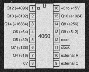
Also, keep these 4060 quick reference cards handy:
The frequency calculation formula is given in 4060 IC datasheets generally assumes VDD is 10V, C is greater than 100pF, R is greater than 1KΩ, and RS (external stabilizing resistor) is larger than 10 times R. In my experience, this formula is accurate only when using genuine 4060 ICs at recommended operating voltages (there’re countless counterfeit chips that didn’t behave well).
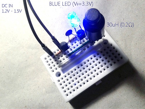
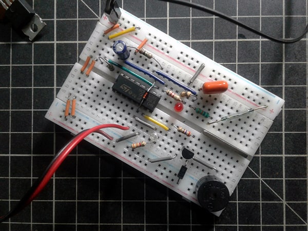
This is a quick view of my breadboard prototype:
Construction
The locker security switch should be fairly easy to construct on a small perf board. I suggest you use IC socket on the safe side – directly solder it onto the board, plug the IC into it the right way round, and you should be okay. After constructing the board, mount it (with the battery pack) in a tamperproof enclosure. The intertwining of the door sensor/switch and external alarm, etc. should present no problems. A connector may be used for the door sensor/switch if required or a pair of thin wires may be brought out directly from the circuit board. While mounting the door sensor/witch inside the locker (in an obscure corner), pay close attention to its changeover i.e. the input port must feel a ‘wire-break’ when the locker door is in the open state. As a final point, you may care to note that you can get prolonged runtimes by using a single-cell (1S) lithium-ion or lithium-polymer battery (3.7V Li-ion/LiPo) instead of the proposed 3V (1.5V x2) dry cell pack.
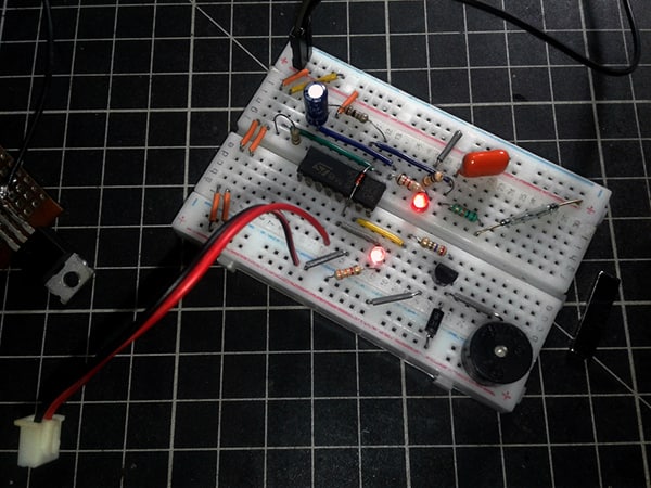
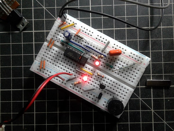
Two more snaps (prototype in the latched state) from my workbench:
What now?
You are now in possession of your very own locker security switch prototype, with an intelligible circuitry, over which you have total control. You can tinker it whenever you want, it’s you who is in command, it’s you who is piloting the inside electronics. Have Fun!