
This is quite a fun little project that can easily help you to build a battle switch for your radio-controlled (RC) model aircraft. The reality is the basic design can be used and/or adapted to be used in different ways for different things.
Outline
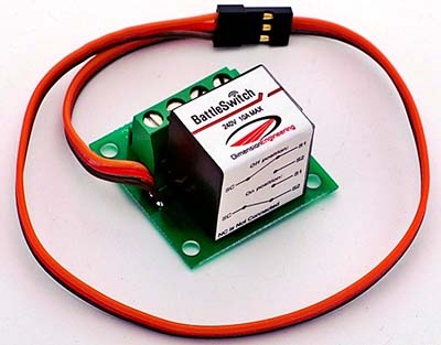
Battle switch is in fact a simple radio remote-controlled switch that you can toggle via your hobby radio control gear. The device typically plugs into a standard hobby radio control receiver as easily as a radio-controlled servo does. You can connect the electric load that you want control through the battle switch’s relay contacts/switch terminals. Depending on the radio channel you use, you will then be able to control the relay by moving your radio’s control stick up or down, left or right, or another method you take (courtesy: http://www.robotcombat.com).
Background
Recently I was contacted by an ardent follower of my blog posts about getting involved mainly with radio remote control electronics. To start off I wanted to build a very cheap device for him to test out some ideas. It’s a bit thought-provoking design but as usual, I started with what the circuit needs to accomplish and then worked to figure out what it should look like. And it worked on the first try!
Restraints
There were two constraints I gave myself for this little project. The first pertaining to the overall budget. Simply I wanted to rely on components I already had and didn’t want to accumulate more parts. The second constraint was that I wanted the final product to be extremely compact. These types of designs tend to focus on function primarily and less on visual aspect. So, the final build ended up using two key parts, a 5V relay for the electric switch and a Digispark for the microcontroller board.
Schematic
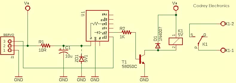
It appears that the schematic is pretty simple and lucid, isn’t it? A servo pigtail with one universal RC connector (J1) is used to give both dc voltage and servo pulse input to the Digispark board (U1). The first I/O (P0) of U1 is configured to receive the RC servo pulses while the second I/O (P1) is to drive the single-pole double-throw (SPDT) relay coil (K1) through a small bipolar junction transistor (T1). The onboard status LED of the Digispark board (hardwired to the second port) will light up when the relay switch is on, and the other way around. If the P0 input of U1 can see an RC servo signal that has a pulse width roughly above 1.69ms (1690us), then K1 will be flipped to its on state (and vice versa).
Note that 5V pin of Digispark takes 4.5V to 5.5VDC. The R-C components (R1-C1) you can find there is inserted deliberately to provide a little bit of extra protection(The 5.1V zener diode is optional), not a very essential thing though.
Code (v1)
This is the Arduino-form sketch/code for Digispark microcontroller. The code is very crude but extensively adaptable, so simply try out new recipes to merge astounding features. Moreover, the mentioned pulse width value is for reference only – you might need to alter the switch configuration ‘on the fly’ to test out the various thresholds (For example: >1.8ms = OFF, <1.2ms = ON). Besides, be ready to adjust the trim on the transmitter stick for best operation.
/*
 * Poor man’s RC Battle Switch/RC Relay
 * Based on Digispark Attiny85 Microcontroller
 * Single-Channel Relay Driver (v1.0)
 * First of all, study the schematic!
 * T.K.Hareendran/09.2020
 */

const int relaySW =  1; // Relay Drive O/P = P1
const int servoIN = 0; // Servo Pulse I/P = P0

int relayState = LOW;
int swp;
int relay0 = 0;

void setup() {

  pinMode(relaySW, OUTPUT);

  pinMode(servoIN, INPUT_PULLUP);
}

void loop() {
  swp = pulseIn(servoIN, HIGH, 25000);
  if (swp > 1690) relay0 = 1; // SEE NOTE!
  else relay0 = 0 ;
  if (relay0 == 1) digitalWrite(relaySW, HIGH);
  else  digitalWrite(relaySW, LOW);

  delay (5);
}
Building
A small Veroboard is adequate for the construction of the whole electronics. You must spend enough time to hide (and watertight) all components in some way – simply pick a small tin can as the enclosure, or go for a big transparent heat-shrink tube to conceal the build. It’s pretty easy – the only thing you really need to see is the power and status indicators sited on the Digispark board.
Wiring
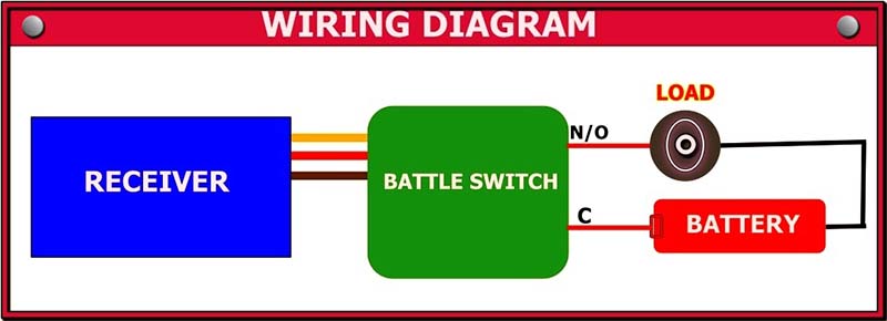
This is an example of the proposed connection diagram. Note that the N/C contact point of the relay is not used here, and it’s of little importance in most applications.
…nighthawk, me?
I started designing the proto version in rainy midnight and ended early the following morning, so it was a quick play as well. Preparing the circuit board, and heat shrinking the build took a little while but it was another pretty cheerful experience. Overall, I’m glad with the final outcome, and excited to see it used outside my home lab!
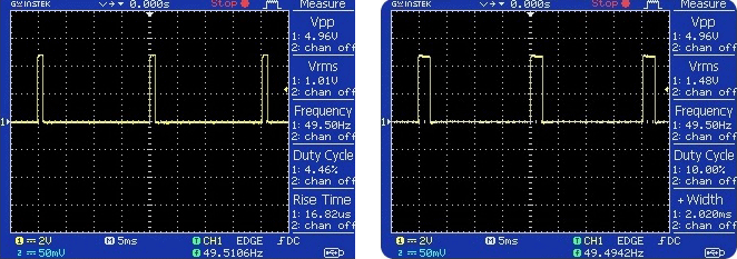
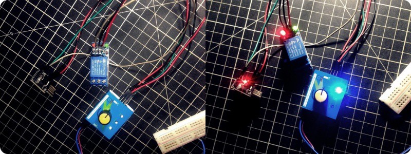
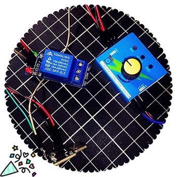
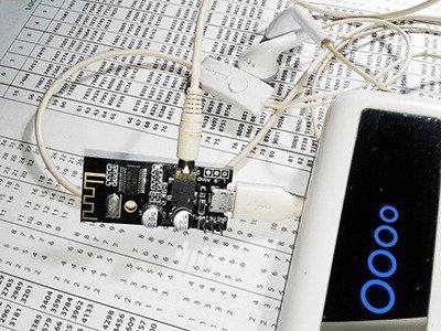
Nevertheless, before going to the actual fabrication of the system, I successfully tested my concept multiple times by means of a servo consistency tester and a one-channel relay module (https://solarbotics.com/wp-content/uploads/52262-schematic_1.jpg). The servo tester is a cheap Chinese make but it delivers servo pulses in 980us – 2020us range (see oscillogram on the right), and my setup toggled the relay upon the receipt of a 1710ms servo pulse input. Closely as anticipated!
Here is a picture showing that initial step toward!
Be attentive…
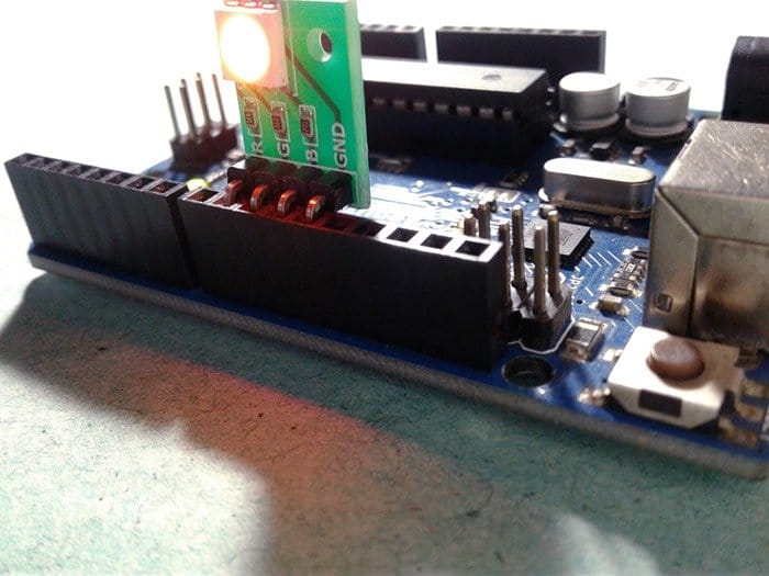
Digispark is very convenient and compact as it has a tiny microcontroller, a USB programming interface, and an onboard voltage regulator. I used Digispark for over one hundred projects yet, and still have some funny ideas in queue. However, it’s worth for you to keep note that Digispark often seems to be incredibly fragile, from both hardware and software point of view. The USB interface is in fact a clever trickery. The Attiny85 microcontroller holds a bootloader program (https://github.com/micronucleus/micronucleus) to allow uploading of new firmware via USB. In its usual configuration, it is invoked at device reset and will identify to the host computer. If no communication is initiated by the host machine within a given time, the bootloader will time out and enter the user program. Since the Attiny series does not support a protected bootloader section, the bootloader resides in the same memory as the user program. Therefore, special care has to be taken not to overwrite the bootloader if the user program uses self-programming features. I’m not sure but guess this makes Digispark much more fragile than the individual Attiny85 microcontroller. I know, in order to achieve the low cost and small size some compromises had to be made. Let it be so, but always try to handle Digispark with great care.
Okay, hope you enjoyed this little post. Whatever you do with the idea shared, I think it’s an easy and engaging do it yourself project for RC hobbyists. I hadn’t done much with RC electronics previously, so I used this also as a fun way to learn!
Code is extremely versatile, thank you
Bob Zurunkle: Thanks, it makes my day to hear that.