There’re many residential electronic pest deterrent circuits on the web, and with some research, you will be able to build one yourself for your pest situation. The most practical and cheerful residential pest deterrent solution is electronic pest control as it needs only little maintenance. Further, such a device is very easy to use and certainly non-toxic!
Of course, there’re numerous do it yourself projects to choose from depending on the application you need. This article describes the construction project of a simple sonic/ultrasonic electronic pest deterrent mainly tailored to residential pets. This do it yourself electronic pest deterrent can hopefully deter rodents, cats, dogs, lizards, and insects. One key advantage of this low-profile microcontroller driven design is that the operating frequency of the device can vary simply by modifying one line of the default microcontroller code according to what pest you are looking to deter. In short, you can make it transonic or ultrasonic at ease!
Well, here’s its complete schematic (v1):
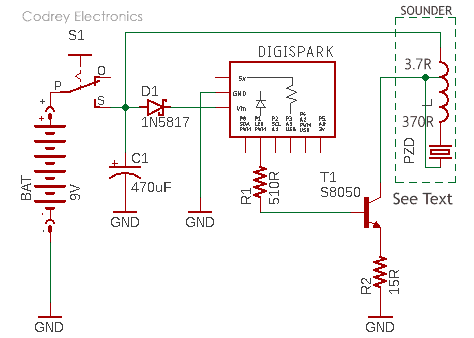
Now see the parts list:
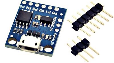
- DIGISPARK: Digispark Attiny85 Microcontroller Development Board
- T1: S8050 NPN Transistor
- D1: 1N5817 Schottky Diode
- R1: 510Ω ¼ W Resistor
- R2: 15Ω ¼ W resistor
- C1: 470uF/25V Electrolytic Capacitor
- S1: Toggle or Slide On/Off Switch (1A rated)
- BAT: Li-ion 9V Rechargeable Battery (learn more https://www.codrey.com/electronics/9v-rechargeable-battery-right-wrong/)
- SOUNDER: Car Dome Tweeter (4Ω impedance minimum)
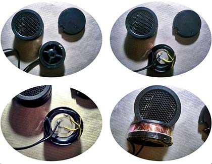
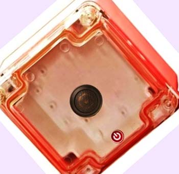
In a common car dome tweeter, you can see a small piezo-disc (sounder element) and a big inductor (booster coil) inside its shell. The inductor functions like an ‘autotransformer’ to drive the piezo-disc aloud. This is the quick specifications of the cheap car dome tweeter I used in my prototype.
- Frequency Response: 5-20kHz
- Sensitivity: 97 dB/W/M (learn more https://myhometheater.homestead.com/splcalculator.html)
- Impedance: 4Ω (Inductance measured by me: 30uH)
- Power Rating: 80W Max
- Sound Dispersion: 90°
- Weight: 20gm
And, this is the inside view of that car dome tweeter, photographed by me (yes, a collage):
As you can see below, the code for Digispark is incredibly simple, and adaptable to Arduino Uno/Nano/Pro Mini microcontroller boards as well. The code is tailored to deliver a ‘random’ 12kHz pulse output thru one I/O of Digispark. Pin 1 (P1) is used by default as it’s hard-wired to the onboard ‘user’ LED, hence enough here to work as a system status indicator (this obviates the requirement of an external visual indicator).
long randNumber; //Random Number
long randNumber1; //Random Number 1

 void setup ()
 {
 }

 void loop ()
 {
 randNumber = random(500, 5000); //Random number in between 500ms-5000ms
 tone(1, 12000); //Deliver 12kHz tone thru I/O pin P1
 // tone(1, 15000); //Deliver 15kHz tone thru I/O pin P1
 delay(randNumber); //Continue to play tone to the time of random number
 noTone(1); //Halt
 randNumber1 = random(10000, 25000); //RandNumber1 in between 10s-25s
 delay(randNumber1); //Stay halt to the time of randNumber1
 }
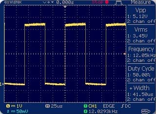
Below is a random scope grab captured while it’s poked into P1 of Digispark wired in my mini breadboard test setup. Nevertheless, I ran the primal code to get other drive frequencies like 10kHz, 15kHz, etc. and all tries worked decently as awaited.
It seems that I’m repeatedly making little projects with Digispark board, eh? Admitted! Personally, I tend to favor the Digispark board over the ‘virgin’ Attiny85 chip mainly because of the price factor: A Digispark board (often a clone) can be had for around half the price of an Attiny85 chip, and the board is loaded with a 5V linear regulator, pin headers, power and user LEDs, etc. Moreover, I get a USB plug for programming the tiny chip over USB. Why would a single Attiny85 cost more than a compact module loaded with the same chip, a voltage regulator, pin headers, and other electronic components? I’m totally clueless!
To get a bundle of Digispark project ideas, and more technical information than you could possibly want, check out the links below:
- https://www.electroschematics.com/learn-to-use-attiny85-usb-mini-development-board/
- http://ediy.com.my/blog/item/72-digispark-diy-the-smallest-usb-arduino
- https://www.codrey.com/tag/digispark/
Design of the Digispark Pest Deterrent is tailored to be operated on a 9V (> 500mAh) lithium-ion rechargeable battery. Anyway, you’re free to use an external 9-12VDC adapter as the power source. Likewise, you can employ another piezo-sounder of your choice but you would need to ensure that’s good enough for the play.
In my opinion, the best practical frequency scale for a residential electronic pest deterrent would be 5kHz-25kHz.

While getting closer to the piezo-disc driver circuit, initially I faced minor difficulties in learning and doing the design maths, but succeeded at last.
Operating a piezo-disc (piezoelectric element/transducer) as a sounder requires an electrical input/driving signal with certain appropriate characteristics. The two key components of the electrical input are the drive frequency and voltage amplitude. There’re a number of driver circuit ideas available to designers. To get a good primer https://www.codrey.com/electronics/piezo-ceramic-discs-practical-thoughts/ provides extensive information.
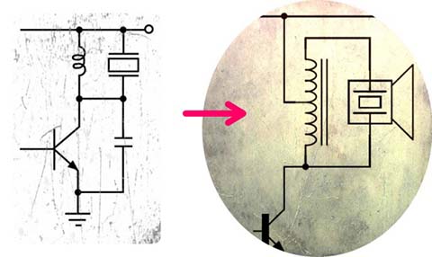
As you might noticed, slightly refactored idea of the typical “resonant driver circuit” (look after the image shown above) is utilized in this design. In principle, the resonant circuit is characterized by the storage and transfer of energy between two elements, which in this case is the parasitic capacitance of the piezo-disc and the inductance of the associated booster coil.
Resonant driver is a simple and easy to build a circuit that has high electrical efficiency and the ability to raise the voltage established across the piezo transducer to be much greater than the input supply voltage. However, it’s worthy to note that a resonant circuit operates best at one specific frequency, and the opted frequency also influences the inductor that can be beefy compared to other circuit elements. Besides, a resonant driver circuit relies on the parasitic capacitance of the piezo transducer (which’s not always well-controlled or characterized while production), and this obviously calls for some extra design work in the lab.
Sidenote about sound pressure level (SPL)
Electronic (sonic/ultrasonic) pest deterrent is an effective, safe, and risk-free way to get rid of those pests from your living area as such a device can effectively change the living environment of rats, mice, and other common pests. Most off-the-rack electronic pest deterrents offers 130dB+/- 15% output sound pressure level.
Noise intensity is measured in decibels (dB). A decibel is a unit that measures the intensity of sound on a scale from 0 to 140. Normal breathing measures about 10dB, conversation about 60dB, and shouting directly in someone’s ear, 110dB. Since the scale is logarithmic, 90dB is 10 times louder than 80dB. It’s important to note that continuous exposure to a loud sonic/ultrasonic sound can cause hearing loss. Length of exposure to the sound is also critical – the longer you’re exposed to loud noise, the more damaging it may be!
For these reasons, it’d be good to measure the sound pressure level (https://www.engineeringtoolbox.com/sound-pressure-d_711.html) of your homemade electronic pest deterrents. Sound pressure level (SPL) is the pressure level of a sound, measured in decibels (dB). In other words, SPL is the ratio of the absolute sound pressure against a reference level of sound in the air. You can use an SPL meter to measure the sound pressure level, which usually displays a range of SPL from 20dB to 140dB (https://www.softdb.com/difference-between-db-dba).
Even though it comes with many limitations, a smartphone is a very convenient and inexpensive method of quickly testing for the presence of sonic and/or ultrasonic sound. So, simply take your smartphone, equip it with an app capable of making a spectrogram of the microphone reading, and see whether you can detect airborne sonic/ultrasonic sounds in a specified area. This is by far the most popular method on hobby electronics world. I will try this and share the results after a few weeks. Meanwhile, if you’re on a train with time to kill, then have a good Googling to get more ideas on this!
Final piece of the puzzle (Enclosure)!
Since the design is centered on a readymade dome tweeter, you don’t need to spend much time on the cavity work to bury a thin piezo-disc. So, drop the maths and simply grab a small transparent/translucent electronic enclosure (or ABS box) to put your entire assembly inside (look below to get an enclosure hint).
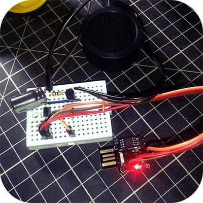
Anyway, I didn’t set my things that way yet! This is my dirty breadboarded model.
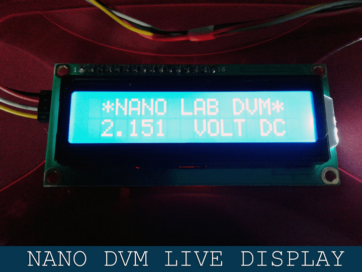
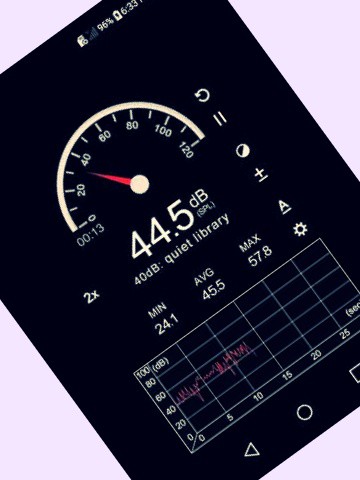
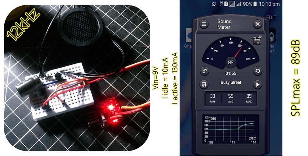
And, a random test shot (Test distance: 15cm). Thanks to the “Sound Meter” Android App!
For a distance attenuation calculator, you may go to this page https://www.omnicalculator.com/physics/distance-attenuation
That’s all for now! Please let me know what you think. And best of luck with your projects out there!