Little version of the audio induction loop receiver presented here can serve a variety of purposes. It is extremely useful for receiving audio from an audio induction loop transmitter or any other source that generates an audio magnetic field!
Ok first off, nothing revolutionary here, just using bits I have sitting doing nothing. This is the circuit diagram (v1) of the audio induction loop receiver.
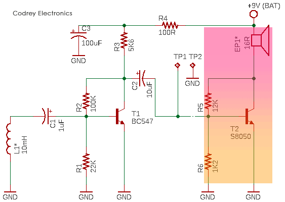
The key component in this circuit is a small inductor (L1). This receiving coil (the pick-up coil) is not particularly crucial – the breadboard prototype was tested with a 10mH radial inductor (ripped out from an old hearing aid) with reasonable results but you can try several inductors simply by listening to the output. It’s worthy to note that coils with too small inductance will sound tinny (poor low-frequency response) and beefier iron core coils will sound muffled.
The remaining components are not very critical. The first BC547 Transistor (T1) can be just about any NPN general-purpose small-signal transistor. The S8050 transistor (T2) is being used as a little audio amplifier to drive a 16Ω small loudspeaker/earphone. In fact, the whole assembly is nothing more than an audio amplifier with a pick-up coil wired to its input and other amplifier circuits might perform equally well. The ‘raw’ audio signal can be tapped through the test points TP1 (Hot) and TP2 (GND) to feed an external audio amplifier catering just a few watts of power. The power supply is nothing more than a “6F22 V battery. Do make sure to get one, preferably a lithium-ion 9V battery that will supply both the voltage and current demanded.
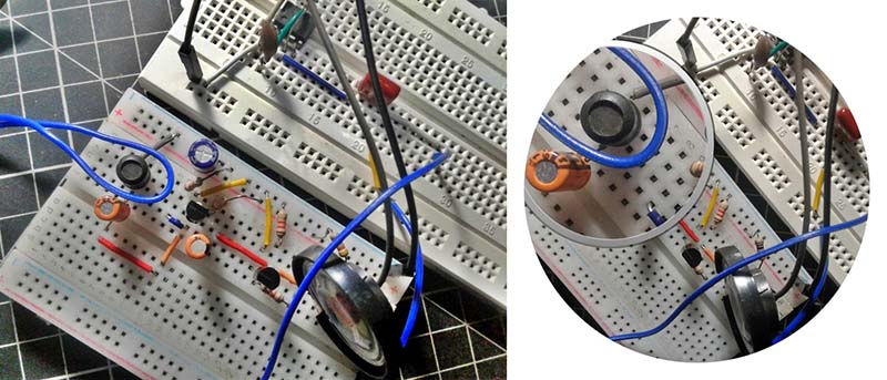
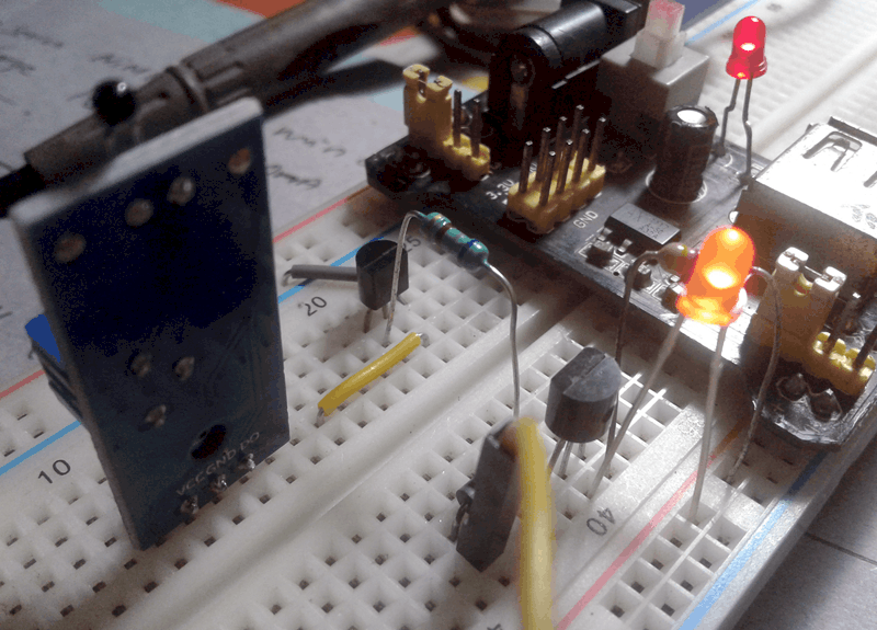
You can first assemble the audio induction loop receiver circuit on a solderless breadboard for initial testing.
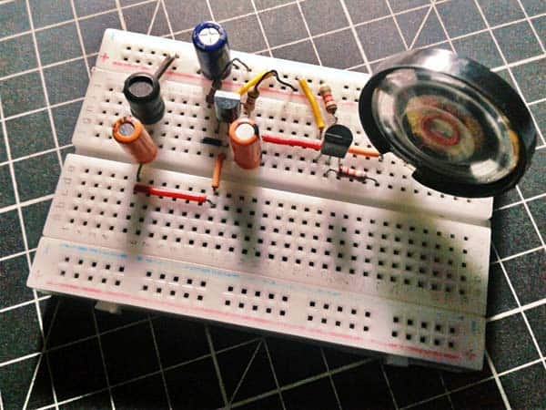
Thereafter, a permanent version can be constructed using a general-purpose prototyping board with through holes and solder pads. In order to reduce power line hum, radio frequency noise, etc., make sure that component leads and connecting wires are as short as possible.
Now I’d like to remark that the one-transistor (T2) audio amplifier isn’t a viable circuit for a number of reasons, but it’s something you should be able to build with what you have handy and get some results. Further, the common 6F22 9V battery is not a trusty power source for driving a loudspeaker because it’s very wimpy, and the loudspeaker needs considerable bursts of current, it has a comparatively high voice coil resistance (16Ω), though. I have deliberately not gone into a lot of technical detail here as the purpose of this was more to point you in the direction of an entry-level solution to an audio induction loop. I will willingly answer any queries anyone has in creating their own audio induction loop by following this idea – just drop a message in the comments box below.
Well, now you’re halfway up the ladder! Yes, you just completed the construction of the receiver part of a crude unidirectional ‘wireless’ audio communication system. This audio induction loop receiver can catch the signals channeled by an audio induction loop transmitter situated anywhere within the ‘audio loop’ and perhaps a short distance outside that loop.
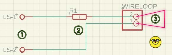
Next part, the audio induction loop transmitter, is simply a tone generator (audio frequency oscillator) connected to a loop of one turn of 30cm long ‘breadboard wire’ that serves as the transmitter antenna. Below you can see the circuit diagram of my ‘test’ transmitter wired around the timeless tiny timer chip NE555.
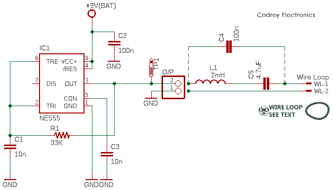
In this schematic, the NE555 (IC1) is wired as a ~1.7kHz tone generator with timing components R1 and C1. Output (TP1) of IC1 drives the wire loop through a 100nF coupling capacitor (C4). To test the system, I attached one end of the wire loop (WL-2) to ground (GND) terminal of the output connector (O/P) and the other end of loop (WL-1) in series with the coupling capacitor to the other terminal of the same output connector. However, you can use the ‘tuned’ LC network (L1-C5) as pointed in the schematic as a replacement for the 100nF coupling capacitor. And that’s all that’s required to get this to work.
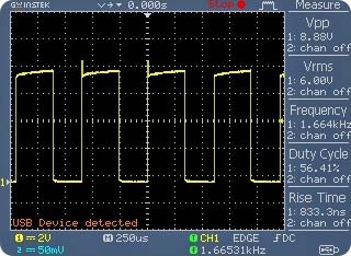
This a casual oscillogram captured while it’s hooked to TP1 of the audio induction loop transmitter circuit (wire loop unplugged).
In principle, an AC current flowing in a wire generates a magnetic field, stronger near the wire. Here, the audio tone signal from the oscillator creates a magnetic field around the wire loop (this field varies directly with the intensity and frequency of the tone output). When the receiver’s pick-up coil is introduced into the field, a voltage is induced across its windings (this voltage varies with the frequency and intensity of the changing field, as well). It should be noted that the magnetic field strength decreases relatively quickly as the distance from the transmitter wire loop increases. Also, the relative orientation of the wire loop and pick-up coil determines the strength of the signal at the receiver end. For example, minimum coupling occurs when they are meeting at right angles, and maximum coupling (at a given distance) occurs when they are lying in the same plane (coplanar). In other words, the wire loop must be perpendicular to the pick-up coil axis.
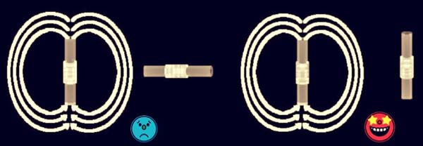
To test your system, make sure that the transmitter’s wire loop and receiver’s pick-up coil are oriented properly. At first, place the pick-up coil inside the transmitter wire loop, turn on the receiver, and then the transmitter. If everything is okay, you can hear the tone at the receiver. Use either a 16Ω mylar loudspeaker or an appropriate earphone/headphone for making soundings. If you notice a power line or other interferences try changing the orientation of the pick-up coil.
Needless to state, I tested the prototype of my breadboarded audio induction loop system with success and got sensible outcomes. I also recorded the received signal while my mylar speaker was singing open-air, and included the raw sound file here for you.
I admit, this little project is absolutely grounded on an old idea that is still alive, and the poor composition might not quench your thirst. But as an electronics enthusiast, this hopefully excites your interest in audio induction loop systems. I’ve always wondered how these magic systems worked, and what it would take to handle the transmission and reception. After some lengthy search, I got some of the answers I was looking for. And this time, I decided to share my quick thoughts with you. It’s clear, I made a few mistakes along the way and literally overlooked some key theoretic considerations. If the thrill of constructing this project is not quite up your street, then I’ve another simple solution!
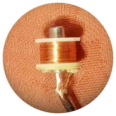
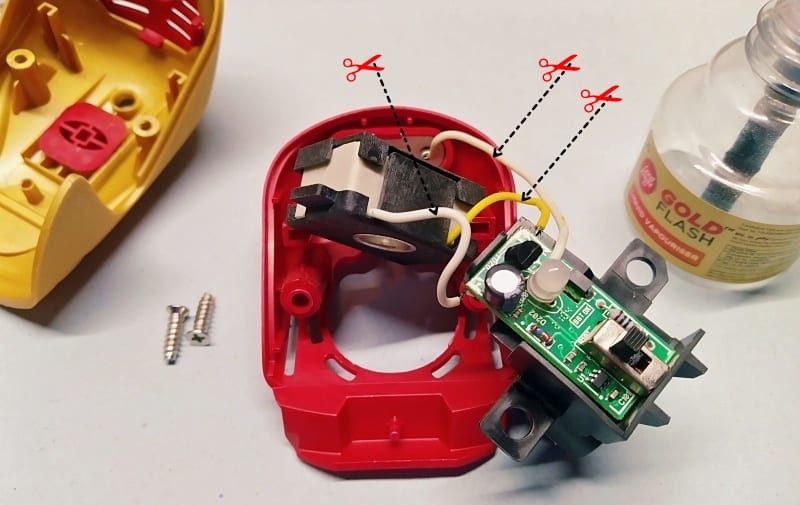
The experimentally inclined might try replacing the existing inductor in the receiver circuit with a receiver coil (pick-up inductor) ripped off from the common telephone pick-up coil (see below).
Likewise, the one-transistor audio amplifier (rightmost in the receiver schematic) can be excluded. If so, just extend the preamplifier output (TP1 & TP2) to an external monoaural headphone amplifier. Try placing an appropriate resistor in series with the output of the receiver (TP1) and the input of the external amplifier, but may not be mandatory.
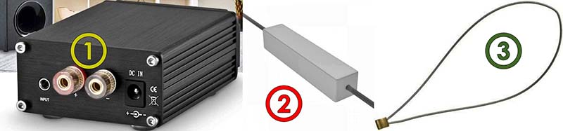
This time, for the transmitter part, simply pick a monoaural audio amplifier that has sufficient output power (5W for example) and connect a big loop (1-3 turns) of single-core speaker wire across its loudspeaker output terminals. An impedance matching power resistor is also essential in this ‘antenna’ setup – the impedance and power rating of the antenna (wire loop) should match that of the audio amplifier. For example, if the audio output is rated at 5W into 4Ω then use a 4Ω resistor with a power rating of at least 10W i.e. twofold. Finally, make absolutely sure that the power resistor is fully suspended in free air – never wrap it in something as it might get red-hot during operation!
You can of course omit this beefy power resistor if your wire loop has a resistance equal to 4Ω or so. However, you still need to use a (small) series resistor because you have created a big wire loop (resembles an inductor) that could cause some instability in the audio amplifier’s core electronics! The addition of a resistor in series with the loop heals it, so include one 1Ω/2W metal-film (or carbon) resistor there.
In the end, I got a pragmatic idea good enough to develop a new system that allows for the broadcast of audio through the use of magnetic fields. A good learning experience, indeed!
Well, now you too have a bit old technique in front of you to listen to your fav audio all day long without another one knowing anything about it. There’re a number of ways for fabricating audio induction loop systems – some are extremely simple; some are highly complicated. Having stacks of ideas for your particular audio induction loop system design can provide for a better resolution.
A cleverly timed swing?

Recently I found an anonymous Gmail (in the spam folder) from someone who’s interested in audio induction loop systems. What really made me curious was he (or she) is using a couple of Chinese wireless speakers – neither Bluetooth nor Wi-Fi. According to him/her, they are “magnetic induction resonance speakers”!
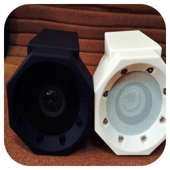
My quick Googling brought back a clear image of the thing being focused. Yes, nowadays we can find plentiful “induction speakers” on the web market. Induction speakers work on the (same) principle that electric currents produce magnetic fields around a wire loop, which in turn can be used to induce a current within a nearby circuit. As a result, it’s possible to create a speaker that wirelessly duplicates audio from the source device. I’m not alone here, ha!
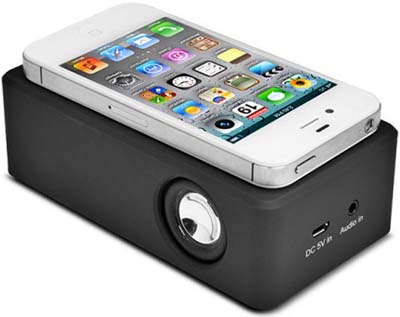
Coming to another new (?) wireless audio technology, the Near Field Audio™ (NearFA™) allows mobile devices to transmit sound to an amplifying speaker within a short distance. As found in a blog post, most existing mobile devices such as iPhone, iPod, iPad, and Android devices are supported by NearFA™. The NearFA™ speaker can capture and amplify the sound of an iPhone (or other mobile devices) if placed next to the speaker. Comparing to other audio transmission technologies such as Bluetooth® or Wi-Fi, NearFA™ is easier to use and lower in power consumption. Further, read https://www.audioholics.com/news/near-field-audio-technology
References
Hello, I find the “induction” transmission very interseting, is it possible to create splitted coils around an (metal) pipeline to send and recieve over significant lengths radio frequencies?
@Kees: I have no idea about this. Sorry. However I have a few projects based on resonant inductive coupling technology. If I learn anything related while making them, I will update you. Meanwhile, you may go through this post https://www.wikiwand.com/en/Resonant_inductive_coupling Thanks!
Hi T.K I’m keen to learn more about inductive coupling and contact a freelance engineer to assist with a project I’m working on. Would you be keen to discuss.
Ryan: I’m afraid I can’t offer my help at this time as I’m busy with several projects. Anyway if you have any questions send them to my email “protected” and I will try to respond as soon as possible. Thanks!