Presented here is the do it yourself electronics project of a simple and inexpensive automatic rechargeable flashlight. You can plug this compact flashlight into a wall socket to charge, and when power fails, the flashlight goes on, serving as an emergency lamp!
Design Description
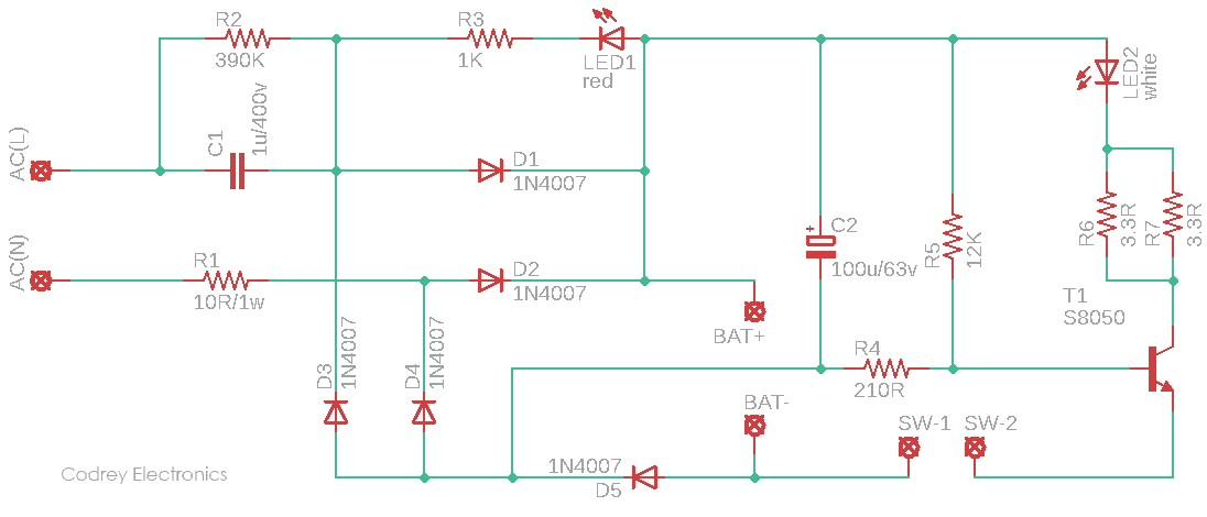
As you can see in the above schematic, frontend of the flashlight is a traditional capacitive power supply centered around a special capacitor (C1) to drop the AC230V input to a littler value, without the need of a bulky step-down transformer. The resistor R1 limits the current inrush when you plug the flashlight into the electric outlet, and resistor R2 is included to discharge the capacitor C1 when you unplug the power supply from the electric outlet. The resistor R3 works as the current limiter for the power supply input indicator LED1.
The rechargeable battery is a small sealed lead-acid (SLA) battery(4V/500mAh). Note that in a common capacitive power supply, there’s a zener diode to limit its output voltage, whereas this circuit just uses the SLA battery to provide a low impedance clamp. While charging, diode D5, pulls the base of the LED driver transistor (T1) down to turn off the light source (LED2). However, when power goes out (or you remove the flashlight from the electric outlet), diode D5 stops conducting, and resistor R3 supplies current into the base of the transistor T1, turning on the white light source LED2, if the flashlight switch is in its ‘on’ position. Resistor R6 is the current limiter for LED2.
Wherefore the electrolytic capacitor C2? Remember, the ‘buffer’ capacitor is a very crucial part in this circuitry because the AC waveform does cross zero 100 times a second and we don’t want that modulates the LED driver transistor T1.
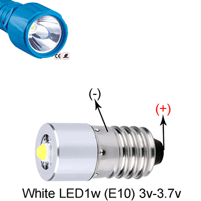
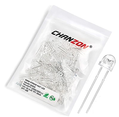
The given circuit configuration allows you to use any standard 5mm white LED as the light source. But it’d be better to use one 5mm white “straw hat” LED (see below) as the ‘flashlight bulb’. The usual Chinese white straw hat LED has a typical forward voltage (VF) around 3.2V at 20mA forward current (IF). It’s a good practice to angle the straw hat white LED from the circuit board since its slightly longer leads can dissipate the heat somewhat.
Key Components
Nothing exotic, this little design is based on a few standard parts that everyone has on hand. This facilitates the building of the flashlight without first having to make a trip to the electronics store around the corner, or order the correct parts from some internet merchant!
| R1 | 10R/1W (MFR) |
| R2 | 390K ¼ W |
| R3 | 1K ¼ W |
| R4 | 210R ¼ W |
| R5 | 12K ¼ W |
| R6 | 1R6 ¼ W |
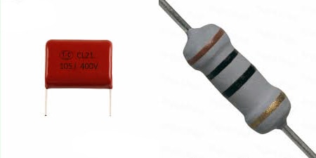
| C1 | 105J/400V (CL21) |
| C2 | 100uF/63V |
| D1-D5 | 1N4007 |
| LED1 | Red 3mm |
| LED2 | White 5mm (Straw Hat) |
| T1 | S8050 |
| BAT | BAT |
| SW | SPST Slide/Rocker Switch |
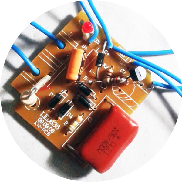
The 105J/400V capacitor (C1) is an epoxy resin coated metalized polyester film type capacitor. (conventional film capacitors are generally classified into metalized polyester films and metalized polypropylene films depending on their materials). Similarly, the 10R/1W resistor (R1) is a metal film type resistor with flame-retardant epoxy conformal coating.
Note that since the capacitor is directly connected to the high-voltage power supply, it’s highly recommended to use only a X2 compliant capacitor in a capacitive power supply. One advantage of those capacitors in this class are that they are self-healing!
Construction Hints
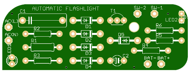
The whole circuit can be assembled on a piece of rectangular general-purpose prototyping circuit board. Of course, there’s nothing to arrest you from creating a customized PCB, but it can easily set you back several hundred rupees. Following figure gives an impression of the proposed PCB. But I’m not that far yet — there’re still some finicky steps in front of me.
After construction, the total electronics together with the battery should be fitted in a miniature, well-insulated plastic enclosure since it is connected directly to the AC power lines. A 3D-printed shell gives the flashlight a deluxe look, not especially essential, though. Note that LED1 in the circuit will glow whenever the flashlight is plugged in – the ac input will drop below the battery positive voltage periodically and illume it.
Hidden Hazards!
A serious disadvantage of the type of power supply used here is that the entire circuitry is directly connected to the potentially lethal AC power line voltage. Moreover, it’s quite natural, when you plug the flashlight into the ac mains outlet, the sudden instantaneous peak of 325V might sweep across C1 and appear at the ‘output’ of the power supply. The first thing that becomes apparent when thinking about capacitive power supply is its extremely dangerous behavior. A step-down transformer, however, would have been too heavy to fit in the purposed enclosure and that is why this type of power supply was chosen.
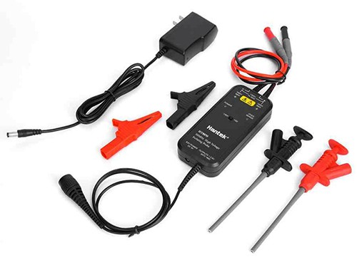
A little aside: While experimenting with a borrowed high voltage differential probe and my oscilloscope, I observed a several hundred-volt spike across the battery while cycling the ac power line input a few times. So just keep in mind that plugging the flashlight into the power outlet will result in a high-voltage spike that sails across the battery. So I think, a 100nF capacitor across the white LED (LED2) is needed to provide protection against the high voltage spike. I honestly don’t believe this has been noticed before by a hobbyist, but I’m sure someone will prove me wrong!
Why a high voltage differential here? Most oscilloscopes cannot measure floating signals with the supplied standard probes. Since the differential probe provides floating measurement capability, it can be utilized for measuring the voltage difference between two test points in a circuit where neither test point is at ground.
More about my dirty trick
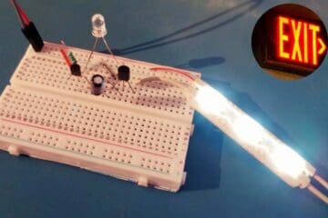
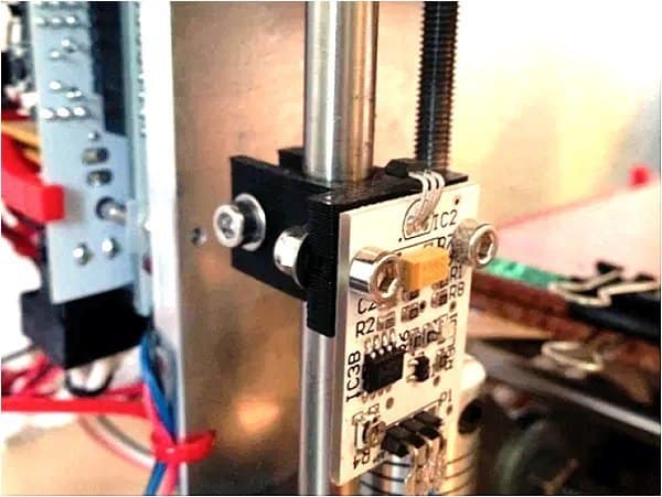
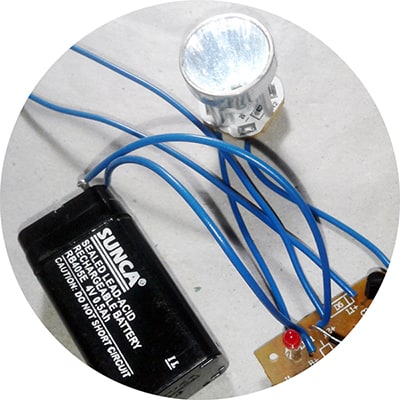
As the frontend of this circuitry is a shameless replica of the ubiquitous Chinese transformerless capacitive power supply, I intentionally used an original circuit board lifted from one defunct emergency light to conduct my quick experimentations. Nevertheless, I reformed the readymade circuit board through the addition and deletion of certain components to cope with my original concept (see below).
At first, I tested my muddy setup successfully with a 5mm straw hat white LED, but later it’s substituted with a readymade white LED flashlight head (see below). The flashlight head holds one white LED chip and two 3R3 chip resistors (soldered in parallel), and of course a small reflector plus plastic lens assembly. It’s marked that its typical forward voltage (VF) is around 3.2V at 40mA forward current (IF). The maximum LED current available in my prototype is all but 50mA.
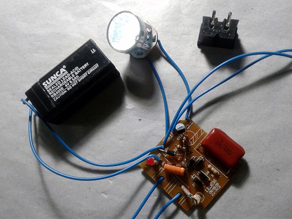
Few more snaps from my workbench:
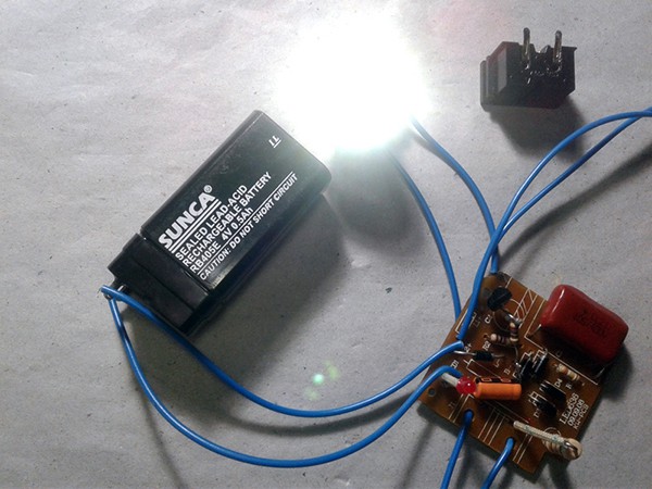
While getting measurements, I found that the maximum voltage appears across the 4V/500mAh SLA battery terminals is about 5.4V during recharging and its nominal output is about 4.2V in ‘free’ state. The nominal voltage, however, falls to about 3.7V when ‘loaded’ by the white LED. According to the textbook maths, this constant current power supply can provide a maximum charging current of 70mA.
Warning: An electrocution hazard exists during experimentation with a transformerless capacitive power supply that’s directly connected to wall power. Since there’s no transformer for power-line isolation in the circuit, an isolation transformer should be used when probing the electronics. Even with an isolation transformer high voltage are present, you must be very careful
Final Thoughts
The design introduced here has some shortcomings, but overall it’s quite usable and does the intended job fairly well. With modification, some of the problems can be fixed, indeed. Next in this series is the do it yourself project of an enhanced emergency light/rescue light. The basic architecture of this little gem has been updated already with some clever electronics, but I still need a few more components to complete the new build. So, please stay tuned!
Extensions