If you forget to switch off the light after leaving a not often used barn, there is a strong likeliness that it might remain lit for a prolonged period of time!
Luckily, it is not toilsome for an avid electronic hobbyist or maker to build a little device to extenuate the unseen issues of absentmindedness. So, get ready to pursue a cheap and cheerful do-it-yourself project idea…
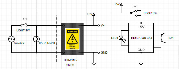
As you can see in the system diagram above, the underlying idea is pretty practicable and straightforward. That is, the barn light watcher circuitry is powered as long as the AC230V barn light is switched on by its on/off switch (S1).
If the door monitor switch (S2) then points out that the barn door has been closed, the alarm sounder (BZ1) mounted outside the barn next to the entry door wakes up. The red indicator (LED1) also reminds that the barn light up there needs to be switched off to save electricity.
Here is the schematic diagram of the audio-visual indicator:
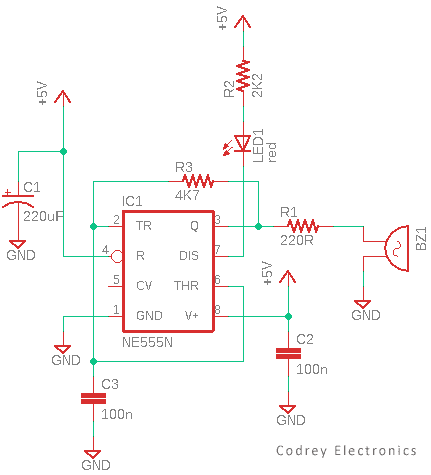
This circuit is simple but efficient. The NE555 timer chip (IC1) is wired as a free-running oscillator to drive a piezo transducer (BZ1).
The pitch of the piezo transducer is set by the resistor and capacitor R3 and C3. As observed, the output frequency is about 1.5kHz at Pin3 of IC1.
Although a regular piezo element has a comparatively high impedance, this drops as the frequency increases due to its inherent capacitive nature. The resistor R1 is added to protect the output of IC1.
The red indicator (LED1) is connected to the open-collector output – Pin7 – of the NE555 IC.
Recommended Parts (see also the following figure):
- IC1: NE555N
- LED1: 5mm Red (low-current type)
- C1: 220uF/16V Electrolytic Capacitor
- C2: 100nF Ceramic Capacitor
- C3: 100nF Ceramic Capacitor
- R1: 220Ω ¼ W Resistor
- R2: 2.2KΩ ¼ W Resistor
- R3: 4.7KΩ ¼ W Resistor
- BZ1: 12mm Piezo Transducer (Ceramic Piezoelectric Disc)
- SMPS Module: HLK-2M05 (5VDC/400mA)
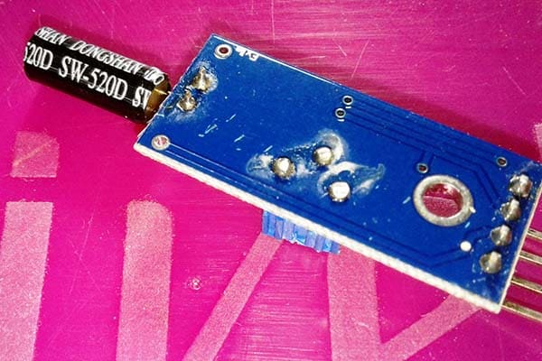
- Door Switch: SPDT Door Switch

The 5VDC/400mA SMPS module seems a bit overkill but, in my view, overkill is not a problem if it does not cost anything more.
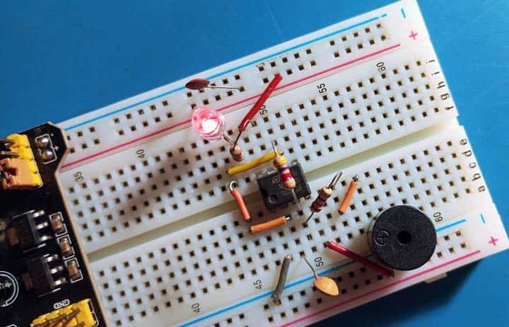
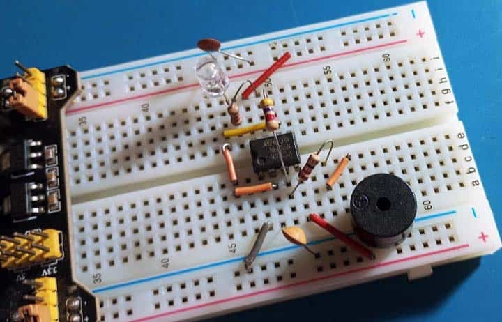
Now see a casual snap of my quick test setup loosely devised on a breadboard…
The system fits easily into a small prototype enclosure or soapbox. Note that some parts of the circuit are at fatal mains potential. For this reason, the assembled circuit must be placed inside a well-insulated case for total protection, with no way that people can touch those risky parts of the circuit.
…And the rest, you can experiment. Have Fun!