Ever lost your radio-controlled aircraft in a jungly field? Well, even a simple lost model alarm detects its location. Following is a couple of design ideas for making your own poor man’s lost model alarm that can be plugged into one of the receiver servo output. The alarm can be heard up to 50-100 meters away in quiet countryside conditions, particularly in the night time.
There’re several methods for making a lost model alarm. Anyway, let me start with an old textbook circuit based on the evergreen 555 tiny timer chip. Note that this is not a decent lost model alarm but should work okay. The ridiculously simple circuity should suit most makes of RC receiver even those deliver low voltage servo pulse output.
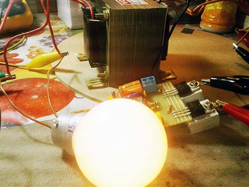
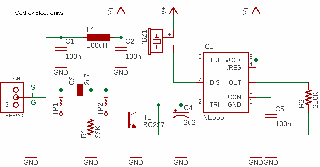
Here, the NE555 (IC1) is configured as an astable pulse generator which sounds an active piezo buzzer (BZ1) around once a second. The BC327 transistor (T1) keeps shorting the 2.2uF capacitor (C4) with each servo pulse input so that 555 can’t get going. The piezo buzzer remains silent during normal flight conditions. Should the model decide to land in a corn or paddy field, then switching off the RC transmitter allows T1 to go open circuit and C4 to begin its charge/discharge cycle enabling IC1 to switch BZ1 on and off. The circuit is shown driving a standard active piezo buzzer but a small electromagnetic/ electromechanical relay could switch several powerful lamps or sounders.
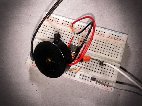
Below you can see my quick test setup on a mini breadboard. As usual, purpose of the quick test is to evaluate the feasibility of the design by implementing a lab desk version of the same as a proof of concept, you might know the idea is viable at this point, though.
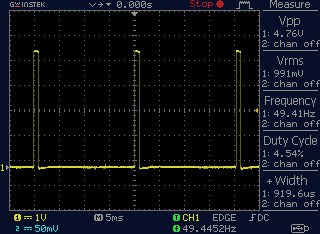
The position of servos used in radio-controlled models is usually set by a pulse-width signal. The base frequency of the control signal consists of a 50Hz pulse train with a duty cycle varying between 5% and 10%, determining the position of the servo. This is the minimum servo pulse delivered by my servo tester (used to test my quick breadboard assembly) as appeared at TP1 in the above schematic.
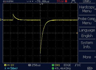
As can see in the schematic, components C3 and R1 handles the servo pulse input. At this point, note that a High Pass filter (HPF) is a special circuit (differentiator) that can convert a square wave input signal into high-frequency spikes at its output. If the 5RC time constant is short compared to the time period of the input waveform, then the capacitor will become fully charged more quickly before the next change in the input cycle. When the capacitor is fully charged the output voltage across the associated resistor is zero. The arrival of the falling edge of the input waveform causes the capacitor to reverse charge giving a negative output spike, then as the square wave input changes during each cycle, the output spike changes from a positive value to a negative value. Remember, each cycle of the square wave input waveform produces two spikes at the output, one positive and one negative, and whose amplitude is equal to that of the input. The rate of decay of the spikes depends upon the RC time constant value of both components and the value of the input frequency. The output pulses resemble more and more the shape of the input signal as the frequency increases (further reading https://www.electronics-tutorials.ws/filter/filter_3.html).
Here’s the waveform (random capture) appeared at TP2 of the schematic with the minimum servo pulse input (~1ms).
Also, note that pin 7 of 555 has the same logic state as its pin 3. The key difference is that pin 3 has an output buffer that can source and sink current while pin 7 can only sink current to ground. Since many 555 datasheets say the current capacity of Pin7 is internally limited to 50mA (but sadly did not described clearly), try to use a low-current, high-output, active piezo buzzer there. Besides, using an inductive kickback diode with the piezo buzzer might be a good idea – just include one 1N4148/1N4007 diode there but in antiparallel with the piezo buzzer.
There’re so many lost model alarm circuits available on the web. Some of them are very complex and expensive designs, usually activated by signal loss or inactivity on RC channel which they’re linked to, after some pre-defined time. And, some other crude designs, like the one presented above, are rather cumbersome in use, as they often activate themselves in undesired conditions, often on the ground, before take-off or after landing. They’re also highly dependent on the model’s power source and radio system.
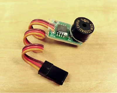
You can of course pick one small microcontroller to build a unique device for you that’s much more than just a lost model alarm. By reading the description of this $11 lost model alarm product will give you many good ideas on adding luxurious features in your next LMA design https://alofthobbies.com/lost-model-alarm-657.html
Previously I built a tiny lost model alarm using Digispark Attiny85 microcontroller development board. Initial version of that LMA has only a few cheap parts that can still be sourced online. The initial version is designed in a different way such that it can be activated manually by a spare channel on the RC receiver when the aircraft goes down. Now I’d like to share the hardware and software of that little project here. As usual, I’ll come up with the full-fledged design of anew lost model alarm (v3) afterwards.
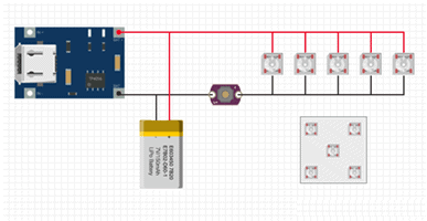
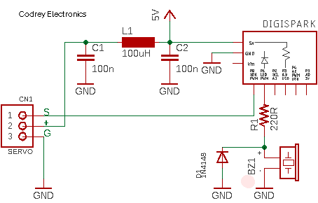
Here’s the complete schematic. As you can see, the piezo buzzer is directly driven by the P1 output of Digispark. This particular I/O also has a hard-wired red LED mounted on the circuit board. Therefore, you need to use a very low current but loud piezo buzzer in this circuit. The Sonitron SMA-24L piezo buzzer (https://www.sonitron.be/products/sma-smat-series/) seems to be an efficient candidate here as it draws only 6.7mA at 98dBA! Note that, A-weighted decibels (abbreviated dBA, or dBa, or dB(a)) are an expression of the relative loudness of sounds in the air as perceived by the human ear.
This is the Digispark code. This code is portable to the common Attiny85 microcontroller, and your Arduino as well.
const int buzzerDrive =  1; //P0
const int servoIN =0;  //P1
int rcinput;
int beeptime = 400; // SET YOUR millisecond delay VALUE!

void setup()
{

  pinMode(buzzerDrive, OUTPUT);
  pinMode(servoIN, INPUT_PULLUP); // Input with Internal pullup

}


void loop()
{

  rcinput = pulseIn(servoIN, HIGH, 25000);

  if (rcinput > 1600) // SET YOUR servo pulse threshold VALUE!
  {
    digitalWrite(buzzerDrive, HIGH); // Beep Pattern
    delay(beeptime);
    digitalWrite(buzzerDrive, LOW);
    delay(beeptime);
  }

  delay(100); // 100mS halt
}
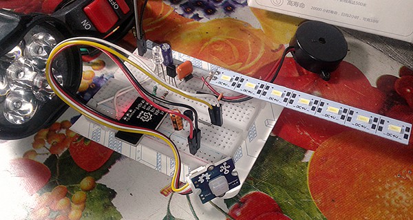
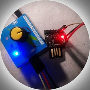
Below you can see a casual snap of my quick test setup. Since there’s an internal LED wired to P1 of Digispark, the piezo buzzer was not used initially, but later I tested the aforesaid SMA-24L piezo buzzer (lifted from a defunct antirape alarm) in this setup. Pretty Perfect!
So that’s it. Okay, this time I don’t walk through this bit by bit. The real-world application of a lost model alarm does need some skill and patience. If at any point you struggled with getting there, never fear there’s a lot of useful resources here and on other websites to help out. Finally, I would recommend testing your lost model alarm(s) with a standalone servo tester (https://robu.in/product/gt-power-3-channel-multi-servo-tester/) and BEC (https://www.dimensionengineering.com/info/bec) before actually wiring it to your receiver (and aircraft). Happy Take off!