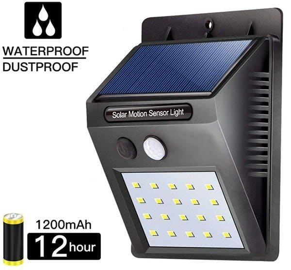
I stumbled across this Chinese solar wall light last week in Amazon while searching for automatic LED street lights. Admittedly it’s not a good fit as a powerful street light but reasonably good for pathway and garden lighting if that areas get amble sunlight on a regular basis. The compact, and claimed to be waterproof, solar wall light has a motion sensor (and a light sensor mechanism) so it wakes up only on nighttimes when a valid motion is sensed within its detection zone, remains lit for about 15 seconds, and then turns off automatically.
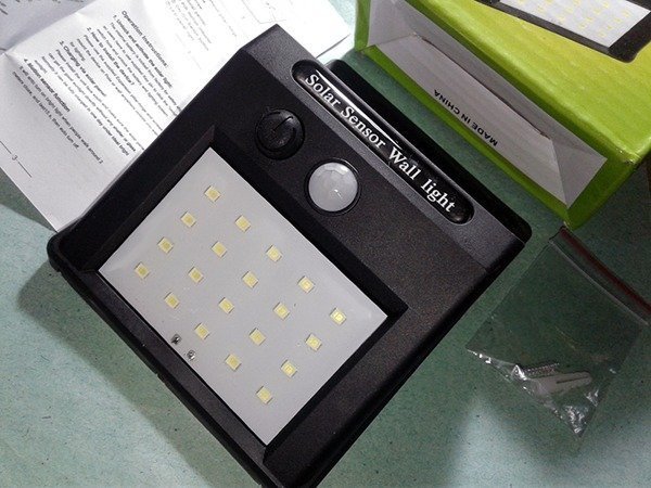
Surprisingly, Amazon seller delivered my item within 2 days just after the buy thus I took an early flight. The solar wall light is designed to be mounted on a wall that has direct visibility to the sky above it as its solar panel sits at the top, perpendicular to the base that the unit is mounted onto. The device itself seats at a slight angle while the motion sensor power button, and the LED panel sit at a much steeper angle. The rear-top of the device contains the small mounting hole that can be used to keep the unit screwed on the wall.
Here’s its specification as printed on its carton:
- Model: JY-6009
- Solar Panel: 5.5v/0.55w
- Li-ion Battery: 3.7v/1200mAh
- LED Power: 0.2W x 20 LEDs
- Night Sensor: <10 Lux
- Motion Sensor: 120 degree/5 meter
- Delay Time: 10sec
- Switch: OFF/AUTO
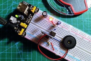
Now to the teardown to look at the internals of the solar wall light. Removing all the 4 screws reveals the inside parts and the enclosure frame.
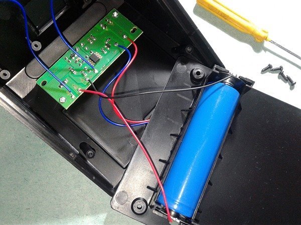
The battery is inserted in a battery holder molded on the rear panel of the enclosure (nice thing) and it’s a 3.7V/1200mAh Li-ion 18650 battery as claimed in the specification. Surprisingly the Li-Ion battery is a type with internal protection circuitry that’s supposed to simplify the design of the charge/discharge supervisory circuits. The ‘loaded’ solar panel, however, delivers a maximum of 4.2V when in moderate sunlight and the output current is just 56mA (may be an inferior solar panel). The waterproof light matrix consists of a bunch of 20 SMD LEDs soldered in parallel on an unfinished PCB , most likely without current limiter resistors. Thin layer of something that’s used to cover the face sadly made the light matrix scratchy and translucent.
Single-sided main PCB of the solar light shows mostly surface mounted devices (SMDs). Key component in the main circuit board is an 8-pin microcontroller used to sample the solar panel output voltage (for night detection) and to monitor the PIR motion sensor output for driving the light matrix in right time. There’s also a 3V LDO regulator to power the microcontroller and motion sensor. An NPN transistor is also there to drive the light matrix, while a single Schottky diode is used in the Li-ion charger section (no more electronics to handle that).
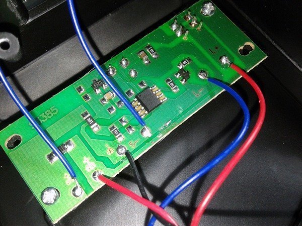
The key part in other side (front) of the PCB is a fully enclosed mini passive infrared (PIR) motion sensor with a plastic lens located in the front. The second component is a small push-lock DPDT power on/off switch, certainly a poor quality one that won’t last a bit longer.
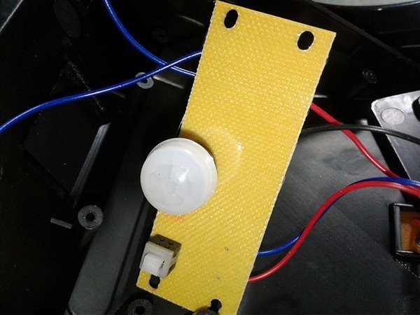
Rather unsurprisingly, part number of the microcontroller was rubbed off by someone. Since the 8-pin microcontroller itself didn’t match up with any of the versions of the common surmise microcontrollers, it’s likely one of the special-purpose ‘mysterious’ Chinese microcontrollers tailored just for solar light applications. Like wise the PIR sensor module is without a part number, but seems like a mere clone of the common AM312 (or AS412) which is a 3-pin digital detector offers complete motion detector solution with all electronic circuitry built into a small sensor enclosure.
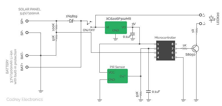
Next is the schematic replicated by me as a reference/study material. Note that original SMD part numbers were carefully decoded for more clarity while I was drafting the schematic.
Another brand of the same solar wall light has a tactile button instead of the push-lock switch that allows for selection of multiple modes like off, dim, auto, on, etc. It’s built around one 16-pin STC microcontroller 15W201S. I doubt that the 8-pin microcontroller used here too has pulse width modulation (PWM) code for “dim” mode but its 3 I/Os (4-6-8) were not used up in this design (perhaps to cut down total production cost).
Since this solar wall light is a motion sensor night light (with timer function to limit the light up duration), a healthy battery can keep it alive for a couple of nights (even if thick clouds persists for a few days) just because of its relatively small current consumption. However, I believe that I’m having issues in understanding design decision made for the Li-ion charger. If the solar panel in my unit gives 4.2V-4.3V, top voltage the Li-ion battery can see is just 3.8 V-3.9V. Let it be, but the maximum current is below 65mA, and availability of summertime sunlight in my area lasts for up to 4-6 hours only. Apparently the design trick used here is ‘slow-rate’ charging of Li-ion battery i.e. charge it below 0.18C constant current and terminate the charge when the voltage reaches 4.2 volts. Even so, that scheme demands a charging current much higher than 60mA, and the get down will kill my Li-ion battery sooner or later. It’s also observed that total current consumption of the LED matrix is around 500mA.
And for the reason, I’d like to reverse engineer my $5 solar wall light to make it better as a fit-and-forget automatic solar lamp. However still I’m happy (and hope remain so) because now I’ve a collection comprising a pretty nice enclosure, a small solar panel, a light panel, a mini motion sensor, and of course one protected lithium-ion battery with its holder that are not otherwise available for $5 indeed. Good enough for a few minor hobby electronics projects!
Don’t assume that the battery is overcharge protected / that the overcharge protection works. I’ve got an identical lamp here in the UK that has blown the end of the battery clean thru the side of case after a long sunny spell…
Thanks your feedback.
Not sure what’s actually put inside certain identical solar sensor wall lights. If the Li-Ion battery is a very cheap type without integrated protection circuitry, then there’s a high risk of fire. Be cautious!
sensor wall light must need to save electricity.
Hi sir, I want to ask something about the solar sensor wall light. I’ve been work about a project that can be use at footbridge. The concept is when people walk , the lamp was bright and when no detected motion it’s turn dim. I’m doing research about it and found this solar sensor wall light in online store that seem similiar. I’ve a request, can you listed what parts that use for my system and how it working. I’m so happy if you can help me with this.
Faris: Frankly, there’re no simple ways to hack the solar wall light as it has an unnamed microcontroller at its heart. Better, you may replace that microcontroller part with an Attiny 85 (or Digispark) to make it work as you planned. You can find PWM codes suitable for multilevel LED dimming everywhere on the web. Also, you can see some related projects elsewhere in this website. Good Luck!
how can i take out the motion sensor so i can just push the button to put it on and to stay on till i push it off
clinton: You may try the following (only if you know what you’re going to do):
1. Refer the schematic (Fig 6)
2. Remove the PIR sensor from the PCB
3. Connect a 5.1K resistor between Pin1 and Pin 2 of the microcontroller
Hopefully, this works for you, but might not be a success as the rest of the process (timer action, in particular) is controlled by the microcontroller. That’s all!
Connect pin 1 to pin 7 on the microcontroller. BTW this page helped me a lot.
Ed T: Connecting Pin 1 to Pin 7 of the microcontroller will kill it! If special features provided by the microcontroller is not necessary (but you still need the motion sensing function), then desolder the uC from the PCB and bridge Pin 2 and Pin 7 solder pads. If so, you may need to change the values of the 51K and 1K resistors, too.
BTW, I did not get it, what’s fun in hacking/reverse-engineering a functional gadget only to degrade its features? Better, try to build a belittled one yourself!
Hello,
I found your article while trying to figure out how should I activate the PIR of my solar lights. On my side, once I turn them on, they remain lit constantly, without shutting down and waking up when movement is detected.
Do you have any idea how I can switch them to the advertised working mode : turn off after a while, turn on when movement detected?
How to fix because my sensor light is not automatically on and off the light. Its steady the light during night
Nancy: Simply put, I don’t know. It’s very difficult to troubleshoot an unbranded hardware online. Ideally, ask in any electronics forum.
Hi, I also have 10 pieces of lamps.
Because the batteries are of very poor quality (this can be seen weighing one existing in the solar lamp and another laptop, say) I decided to give up their batteries and connect them in parallel to a 3.6v / 7Ah power supply with backup but I encounter a problem, not all the lights come on, they turn on randomly and I don’t understand why, you can help me with a hint.
By the way, I have three models of such solar lamps, all with 8-pin microcontroller and unmarked. It should be mentioned that lately I have been encountering more and more Chinese with unmarked pieces, I think I do it out of malice!
All the best!
Mitica: This is a very cheap solar lamp and has no room for serious hacks. Obviously, the solar panel does not have enough juice to charge a 7Ah battery. Also note that its light/dark detection system relies on the solar panel, which means that the motion sensing lamp circuit is activated only if there is no sensible output from the solar panel.
To be honest, I have no particular interest in revising this old article. But in the future I will try to bring the project details of the new and hackable solar lamp. So stay tuned. Thanks!
Hello,
I think I was misunderstood or maybe I didn’t explain correctly.
I don’t want to charge the 7Ah battery with the solar panel, I try to power all 10 solar lamps in that battery, but they don’t all light up properly, and that was the problem. I mention that I canceled the battery from each lamp
Mitica: Now it’s more clear to me. Thanks!
Note that, the voltage level measured at the ends of the solar panel is high, it means that there’s enough light outside, hence the microcontroller disables the LED driver.
So, give it a second try with your 7Ah battery but only after disconnecting the solar panel(s) wires from the circuit board(s).
If the LEDs still do not light properly after that, let me know. Good Luck!
Hello! My Bro
If I want to connect siren speaker 12- 24 volt on this circuit while it can work on day time and night time still likly delay for 10 sec how can I make it and where does the position of circuit? or I shoud have some device to add them.
Thank you very much.
D.Wanit
@Wanit: As already said, this is a very cheap solar lamp built around an unknown microcontroller, and has no room for serious hacks. Another DIY project similar to the one you requested will be published here later. Thanks!