Presented here is the basic circuit of an over-current detector built around a handful of easily available and inexpensive electronics components. This simple circuit for DC devices wakes up when the connected output load draws excess current and activates a digital output that is compatible with almost all microcontrollers. I have used this pretty basic circuit with nifty success for many months, so, let me begin this new article by sharing the tried and tested schematic drawing.
design description
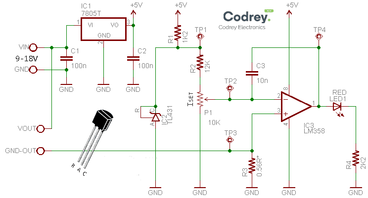
First segment of the circuit is a linear fixed voltage regulator 7805 (IC1) to provide a stable 5VDC to the rest of the electronics. The recommended DC input supply is in 9V to 18V range, and so you can use the circuit for watch and direct devices work within the same range (9V-18V). As you are aware, the 7805 IC is a 3-terminal 5V/1A positive voltage regulator employs internal current limiting, thermal shut down, and safe operating area protection. Even though the absolute maximum input voltage indicated in the datasheet is 35VDC, and the typical dropout voltage is 2V (at 1A, TJ =+25 oC), I still want to go with the 9V-18VDC input.
Next key component in the circuit is the TL431 programmable precision reference (IC2). It serves as a reference voltage generator as a non-standard reference voltage (2.5V) is needed here. The 2.5V reference (TP1) is then reduced to about 1.1V maximum (TP2) via a potential divider formed by the 12K fixed resistor (R2) and 10K multiturn trimpot (P1).
The final part of the circuit is built around one-part of the quite common LM358 op-amp(IC3) which measures a low voltage drop across the 0.56Ω current sense resistor/shunt resistor (R3). The op-amp is essentially wired as a comparator. When the voltage exceeds a set point (TP3), the red indicator (LED1) comes on to raise an alert. This output (TP4) can also be used to drive another circuitry preferably via a standard opto-coupler. Note that the shunt resistor is placed in the negative (0V) rail, so the method is known as “low side” current sensing.
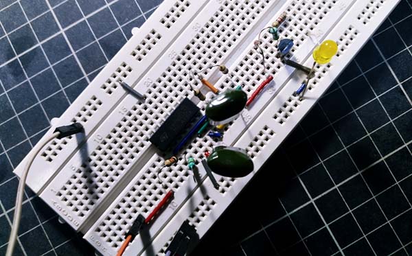
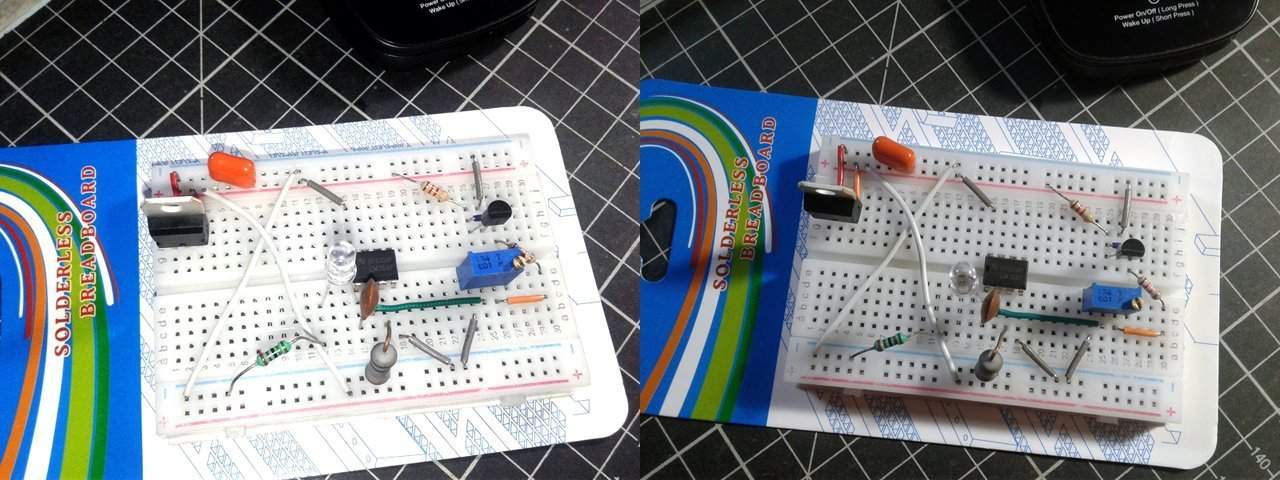
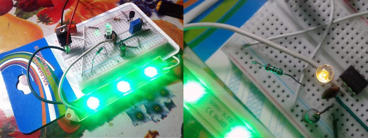
You can see the photograph of my quick breadboard setup below.
the crude maths
With the 0.56Ω shunt resistor, and 1.1V reference, you can use this circuit to handle load current up to 2A. However the shunt resistor must be a type with minimum 5W power rating. The ‘threshold current’ calculation is simple – if the reference voltage is 1.1V, then the threshold current is roughly VREF/R3 = 1.1V/0.56Ω = 1.96A = ~ 2A! Anyway, it’d be better to derate this calculated ‘capacity’ by a factor of 2 (or 4) in order to reduce the inherent voltage drop across the current sense resistor (the temperature rise as well).
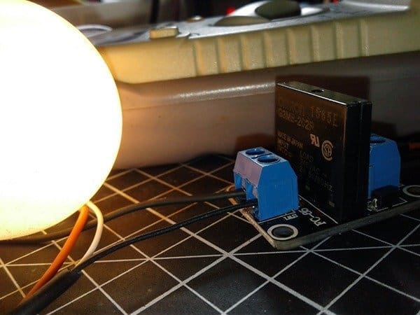
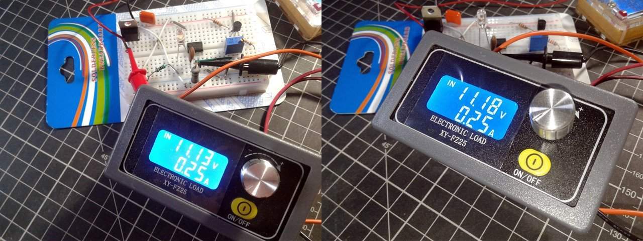
Here is another snap from my workbench taken while I was testing my breadboard assembly through with a Chinese electronic load tester. At that time, the setup was powered by a bit weak 12V SLA battery sitting around, with the threshold current tuned to 250mA.
get a better shunt
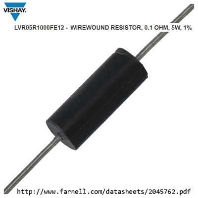
Admittedly, this canonic design has its own flaws, but it’s certainly a quick and easy add-on solution for projects with power LEDs and/or laser diodes. Besides, it works great for sensing large overcurrent situations like ‘end of line’ state where a motor hits the end stop and the current draw jumps up high. My prototype still sense the threshold current set point reasonably, and the trimpot provides a good range of adjustability of the current set point, generally a range of +/- 20% around the set point. However, If you need better than that it is better to replace the current sense resistor (R3) with a new 0.1Ω/5W precision high power shunt resistor (see below). You should also substitute the 12KΩ resistor (R2) in the voltage divider with a higher value one – 62KΩ for example. And, dust the calculator!
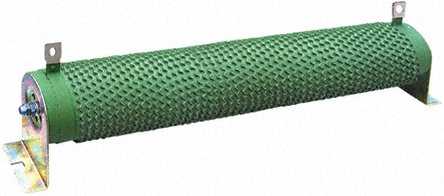
Then why I chose the 0.56Ω current sense resistor at first? The answer is simple – it’s the one and only <1Ω value resistor handy at that time. Frankly, I bought a batch of precision wire-wound power resistors from a reputed seller in China, but the slow boat was further delayed by the ‘corona’ virus tragedy. Sadly my packet didn’t get a way to land in India as yet!
look ma, op-amp!
Also you need to look at certain pointers for LM358 IC based designs. While there are numerous single supply op-amps that can sense at the negative rail, the LM358 is the cheap one available everywhere. The LM358, not a rail-to-rail op-amp though, offers several distinct advantages over standard op-amps types in single supply applications. The common mode input range includes the negative supply, thereby eliminating the necessity for external biasing components in many applications. The output voltage range also includes the negative power supply voltage. The LM358 can operate at supply voltages as low as 3V or as high as 32V.
When it comes to the op-amp (operational amplifier) parameters, note that ‘input offset voltage’ is the difference in voltage between the inverting and non-inverting inputs (zero volt is perfect but a real op-amp has no zero-volt output with zero input), and the ‘common-mode input range’ is the range of absolute input voltage under which normal operation may be expected (0V to VCC-2V is common). Note that LM358 when used as a comparator, only one input needs to be within the common mode range. Op-amps generally do not make good comparators, however, when using LM358 as a comparator, the key DC parameters to consider are input offset voltage, input common mode range, low output voltage (VOL) and high output voltage (VOH). It is important to maintain a valid input common mode, otherwise phase reversal may occur. Further, the input common mode voltage of the op-amp will be the same as the least positive input voltage. For example, if one input is 2V and the other input is 3V, the common mode voltage would be 2V. The voltage of the other, higher voltage input doesn’t affect the input common mode voltage (reference – www.ti.com).
Oh, I missed that – common mode voltage is also known as input voltage swing. Okay, let’s look at how input offset, common mode voltage, and output voltage swing are typically defined on a datasheet.
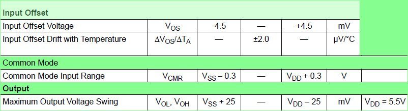
The above information is gathered purposely from the datasheet of MCP6001 op-amp, which is a rail-to-rail input/output, low-power op-amp designed for general-purpose applications. See the ±4.5mV input offset voltage, and the ±2 μV/°C drift with temperature. Also, see the minimum and maximum common mode limitation, and the minimum and maximum output voltage swing. Applying an input common voltage below or above the specified will result in nonlinear output, while driving the output below or above will cause the output to become nonlinear. Amplifiers which can accept common mode input voltage ranges up to the power supply rails, and can swing the output voltage near the supply rails, are referred to as rail-to-rail amplifiers.
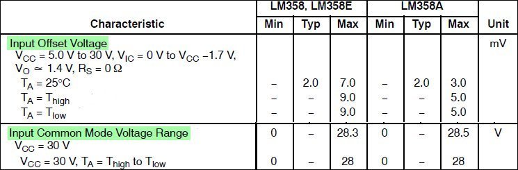
Looking at the LM358 op amp over again, the typical input offset voltage is 2mV, and the recommended common mode range is 0V (relative to the negative supply) to Vcc-2V over the full temperature range. However, the actual upper common mode range varies by approximately 4 mV/°C, with cold temperatures reducing the upper limit of the common mode voltage range.
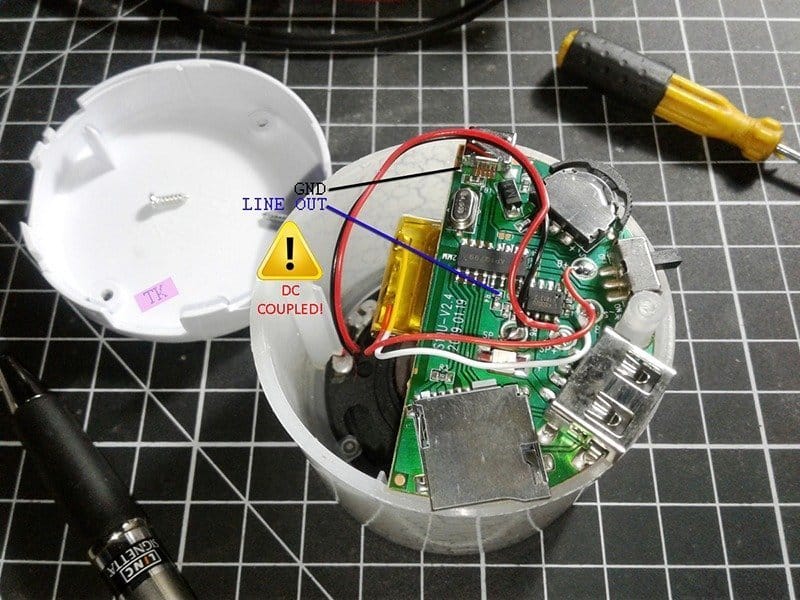
Back into the circuit idea introduced here, I made a second test with one 12V/50mA green LED stick. I powered the setup up through a variable dc power supply. Since I observed about 30mV voltage drop across the 0.56Ω current sense resistor at 12VDC input, the trimpot is tuned to get about 34mV at TP2. Thereafter I increased the output load (LED) current simply by raising the input dc supply close to 13VDC for a while. As expected, the indicator LED comes on to notify me about the over-current situation Yes, it worked!
Finally…
There are countless breakout boards/modules available on the market ready to measure the current with microcontrollers, but I have never seen a low-cost module that is dedicated to indicating an over-current situation. This circuit is also good for other dc loads besides lamps and motors if you need a system to detect over-current conditions or catastrophic components failure etc.
Therefore, for those who love self-construction and also to understand the functioning of the electronic circuitry, I suggest to carry out this little project. This one is a fairly accurate over-current sensor while using common and cheap components. Have Fun!