A budding electronics hobbyist often needs to pick crystals of right frequency for homebrew projects. To make that task a little more cheerful, I’m introducing this simple crystal tester circuit. 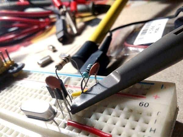 It’s basically just a very basic oscillator circuit utilizing a handful of common parts. The output of the crystal tester circuit can be connected to a frequency counter or digital multimeter with frequency readout to determine the accurate frequency of a crystal. Or it can be used as a front-end adapter for microcontroller based crystal tester projects.
If you need to test some crystals for projects you’re working on, you can easily find countless crystal tester circuits on the internet but lacking one thing or another. Here’s my first version of the crystal tester circuit, actually a meliorated adaption of a timeworn circuit I took from the net. The given circuit, designed to work from 5-12V dc supply input, can be used to evaluate standard crystals having got frequency around 20MHz.
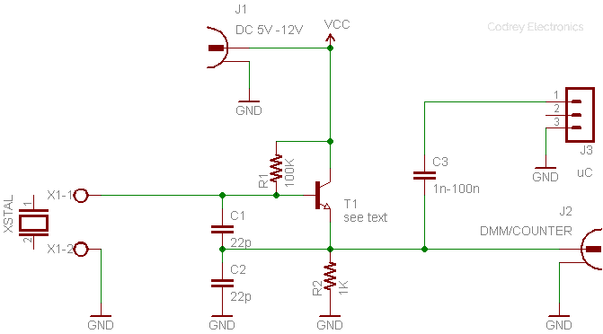
The circuit is a standard Colpitts oscillator. Here, T1 provides the gain, and oscillator feedback is via C1 and C2. The oscillator’s output is taken from the emitter of T1, and it’s ac-coupled via C3 which then also goes to the output terminals. Even though the BC547B provides enough gain, and I was able to test many standard crystals up to 16MHz, I think the C9018 RF transistor would probably give better results. As it turns out, my component drawer currently lacks such RF transistors, a situation later to be resolved by ordering those from one of my Chinese vendors.
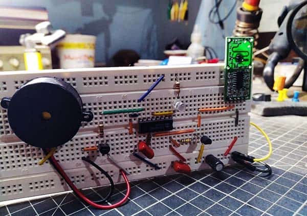
To carryout the quick test I made my basic circuit on a breadboard as shown below. Anyway, you’re advised not to follow that practice, instead solder all components closely on a very small perforated circuit board, and trim down excessive leads of all components soldered on the circuit board.
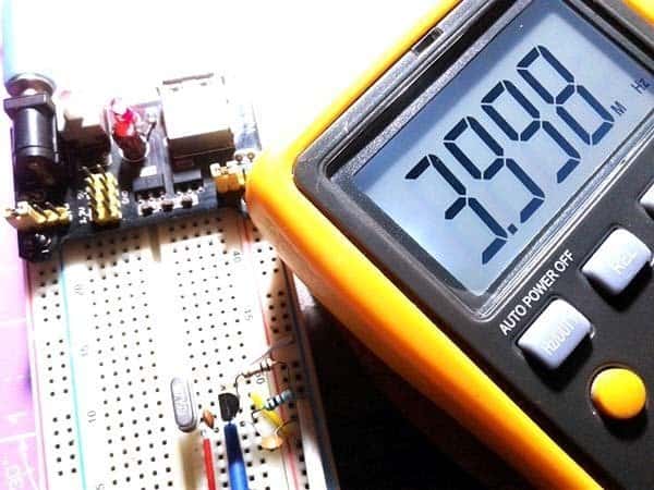
While I was testing the breadboard prototype, I randomly plugged a few known good crystals (thanks to my imported precision crystal tester) into the crystal test points and verified the output with one of my trusty DMMs that has a moderately high-impedance 30MHz frequency counter input. See the test result of a 4MHz crystal as displayed by the DMM’s frequency counter.
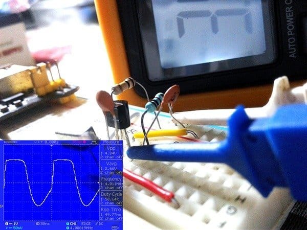
I also tested it with one of my DSOs. The most pleasant result was that all of my standard crystals worked in the circuit without any problems at all.
Note that many 32.768kHz watch-type crystals and several ceramic resonators did not work with this tester because such types require rather different oscillator circuitry to work correctly. This also applies to some higher frequency “overtone” crystals (they may be oscillate on their fundamental frequency, that’s right). For a Colpitts oscillator runs on 32.768KHz, you can go through this do it yourself experiment https://softsolder.com/2017/04/07/colpitts-oscillator-at-32-768-khz/.
Another quartz crystal oscillator tryout
You can easily build crystal oscillators using bipolar junction transistors (BJTs) and field effect transistors (FETs). As clearly stated (and you may know), the wide range crystal tester circuit presented here is merely a Colpitts oscillator but with its LC tank circuit (parallel resonant circuit that provides the feedback oscillations) has been replaced by the quartz crystal under test. One important thing to consider is that the BJT used in the circuit should be adequate to operate at switching speeds well above the fundamental frequency of the crystals intended to be tested.
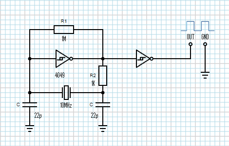
Well, now to the construction of a basic 10MHz CMOS crystal oscillator. See its circuit diagram below. In this circuit, the crystal oscillates at its series resonance frequency. The first inverter gate is initially biased into the middle of its operating region by the 1MΩ feedback resistor (R1) to ensure that the Q-point of the inverter is in a region of high gain. The second inverter gate is wired as a buffer between the oscillator output and output load.
A common transistor based crystal oscillator will give you a sinusoidal output waveform. However, this CMOS crystal oscillator outputs a square wave because of the digital logic gates in the circuit. Also note that the maximum operating frequency counts on the switching characteristics of the logic gate used in the design.
Naturally, I’ve had some advanced do it yourself crystal tester projects, and there will be a follow up so stay tuned. In the meantime, you can take a look at this article that neatly covers the significant performance characteristics of crystals, which include resonance frequency, resonance mode, load capacitance, series resistance, holder capacitance, motional inductance and capacitance, temperature calibration, and drive level – https://pdfserv.maximintegrated.com/en/an/AN726.pdf
I need a crystal tester ckt that will test my 100 khz calibration crystals.
I have a scope and counter.
Most tester designs won’t work below 1 Mhz.
Any suggestions?
Walt: Hope this link helps. Else let me know. I’ll dig a little further. Thanks!
https://www.radioexperimenter.us/rm-1967-03/ant-1.html
(sorry for the quick reply as I am very busy right now).