In this article I’ll show you how to capture sound signals on the Arduino and start some interesting experiments on it.
Look for and gather a sound sensor module
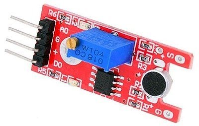
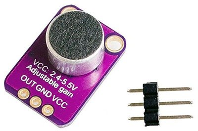
For the experiment initially you need a small microphone and a pre-amplifier to put the voltage range into 0-5V as required by the I/O ports of Arduino. A quick and cheap approach here is the use of a pre-wired Sound Sensor Module like the one shown below. It has a LM393 comparator chip and a multi-turn potentiometer. There is a Vcc pin (+), a Gnd pin (G), an Analog out pin (AO) and a Digital out pin (DO), in addition to two LEDs (L1-L2). An advantage of the presence of that trimpot is that it allows you to set a threshold so the module can deliver a digital output when the sound level is above the pre-defined threshold. The sound sensor connected across the Signal (S) and Ground (G) input points is a common electret condenser microphone (ECM) – the so called condenser microphone (button microphone).
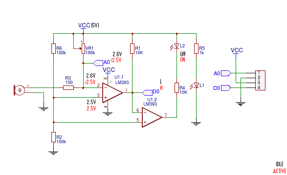
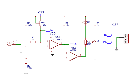
The schematic of the module is same as the one you can find below. I borrowed the image from a Chinese site but it’s a verified circuit diagram.
As the first step I would suggest you take a few moments to connect the sound sensor module with your Arduino Uno for a quick test experiment. Connect pin “+” of the module to 5V, pin “G” to GND, and pin “DO” to D2 of the Arduino board. After the hardware setup, insert the following test sketch into the Arduino IDE and upload it as usual. Now you can see the results in the serial monitor window of the Arduino IDE.
void setup(){
Serial.begin(9600);
pinMode(2, INPUT);
}
void loop()
{
if(digitalRead(2) == 0) Serial.println("No sound detected!");
else Serial.println("Sound Detected!!");
delay(1000);
}
Actually the sound sensor module is a simple peak detector, so at first you should adjust its multi-turn trimpot (VR1) in a way that the signal indicator (L2) lights up only when there’s a certain level of sound. You can make some sounds at different volume levels and see how your sound sensor module responds. Then it’s easy for you to sweep and lock the trimpot for desired threshold for your sound signals.
Now the only choice is to refuse
If you carefully examine the module’s schematic you can realize that the sound sensor module is not a useful module for sound analyzer experiments/projects on Arduino. Here, the microphone on the sound sensor module picks up sound and the comparator compares that against a set threshold and sets the digital output (DO) accordingly. Its analog output (AO) is not an amplified output, but a mere extension from the inverting input (-) of the LM393 comparator i.e. just a raw voltage dc-coupled output from microphone, leaving it useful only for knowing if there is or isn’t a sound!
A better chance of success
It’s note worthy again that the trimpot in the module sets the threshold for the peak-level detector, though it also introduces a little gain effect for the microphone which has an inbuilt field effect transistor. This results in a ‘somewhat’ analog amplifier circuitry with a ‘poor’ offset adjust, however, not recommended for serious Arduino audio analyzer applications. A typical button microphone puts out from less than a mV to a few mV only, therefore you need to amplify the raw microphone output by many folds to get a uC-compatible (and clean) output signal. So, it’d be better to opt for another suitable microphone amplifier module such as the one built around MAX4466 sold by most online suppliers. The MAX4466 chip is a unique op-amp specifically tailored for use as a microphone amplifier, which makes the module a great player and eventually a good choice for the proposed sound analyzer projects.
For those looking for do-it-yourself ideas rather than buying pre-wired circuits, I’ve a couple of other tested & untested op-amp based microphone amplifier circuits. From an email exchange with a friend abroad, I got a page that presented a neat construction project based on LM321. The op-amp chip in the design has a ‘gain-bandwidth’ product of 1 MHz, hence the maximum available bandwidth is 10 KHz (with gain of 100). Seems good!
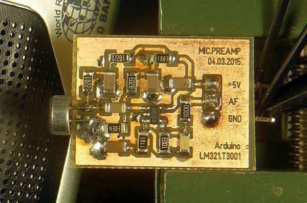
Here’s the original link of that cheerful microphone preamplifier project page https://www.changpuak.ch/electronics/MicrophonePreamplifier.php
With a handy microphone preamplifier you can use ADC of Arduino to start sound level measurement/sound analyzing experiments. I’ll come up with a full-fledged do-it-yourself post soon. Meanwhile you can refer/try one similar audio project from Arik Yavilevich’s blog (https://github.com/ayavilevich/ArduinoSoundLevelMeter).
Oh, I missed that…
One thing that I had forgotten is to show you how my experiment with the ‘useless’ LM393 module is. Well, I’ve done a funny experiment with an “analog read” sketch, and here’s the serial output at various sound levels.
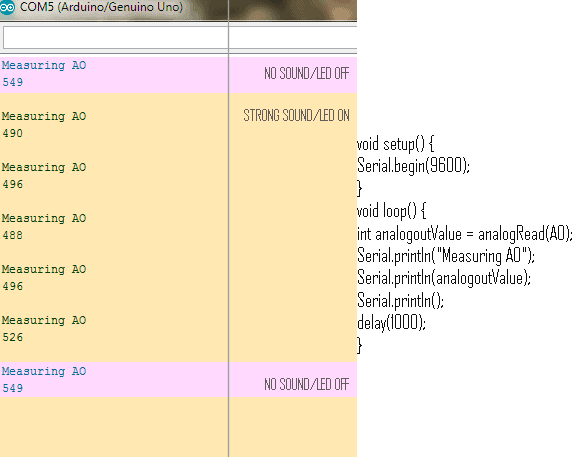
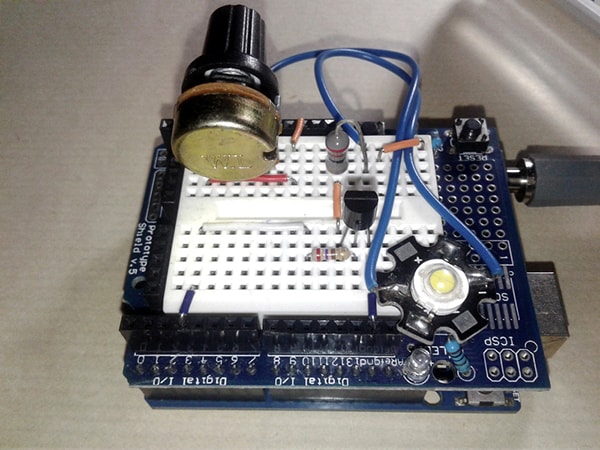
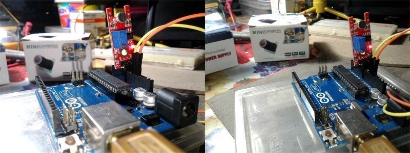
The experiment was conducted with AO of the sound sensor module connected to A0 of Arduino Uno, and the trimpot was aligned to switch the signal LED off at normal sound level (AO voltage near to 2.7V in idle – no sound – state). Below you can see quick experiment snaps from my workbench.
Next is the same first schematic but updated with observed voltages measured by a digital volt meter. And finally, I’d like to see your thoughts here!