With the start of a new year, I wanted to share more thoughts on Endstops! How to construct an endstop myself? This is by far the most common question I hear from 3DP tyros. So it’s time for me to document basic information about 3D printer Endstops, especially useful for those who aren’t much familiar with the 3D printer electronics. Let’s get down to learn now.
Endstop explained
The stepper motors in a 3D printer must know when they have reached the limits of an axis. For this purpose you can use Endstops, and in principle it’s possible to connect up to 6 Endstops. However, basically you needs just 3 Endstops – Y-axis endstop, X-axis endstop, and the Z-axis endstop.
Although 3D printers are extremely accurate and precise positioning systems, note that a 3D printer does not move its print head to a location in absolute coordinates. Rather, movements are made relative to the current position of the print head. So at the beginning of every 3D print, the 3D printer must move the print head to a starting position, which the 3D printer firmware considers to be the origin (0, 0, 0) point called “home”. Starting every 3D print from the same home position allows the 3D printer to reference its movements. Therefore, one endstop switch per axis is required to tell the 3D printer when that position is reached.
Mechanical endstop
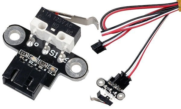
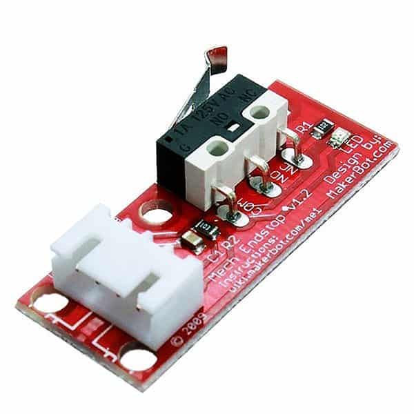
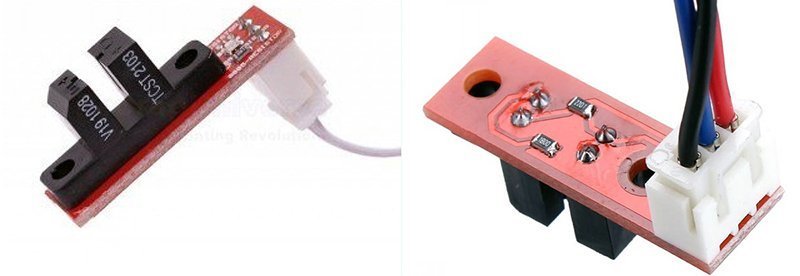
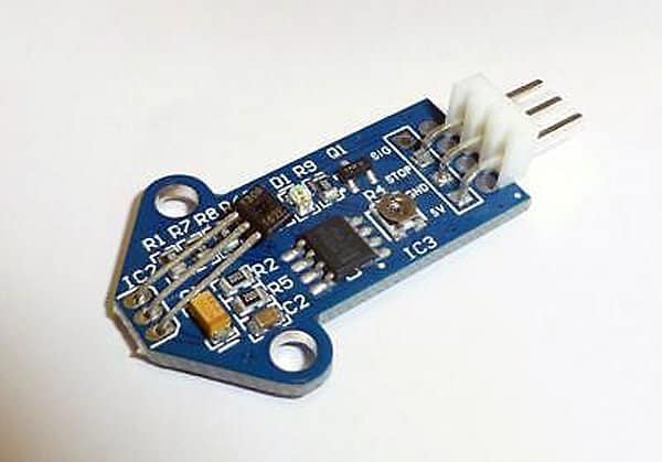
This is the simplest and widely used type of endstop, placed on each axis. The mechanical endstop is actually nothing else than a micro switch, however, to make things easier, you can buy a complete package that includes the endstop module and a connection cable for cheap. Below you can see the photograph of a “RepRap Standard Endstop v1.2”.
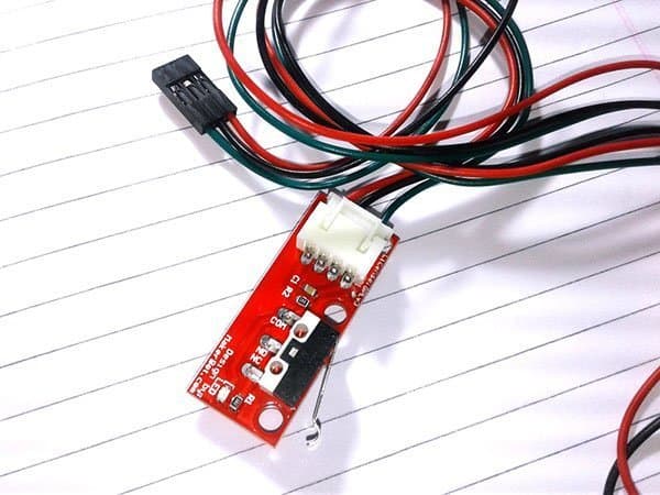
The mechanical endstop is actually nothing else than a bare micro switch (changing the switch state signals the electronics). The standard endstop (v1.2) pictured above (designed by Makerbot) has a 4-pin connector, marked C (common), NC (normally closed) and NO (normally opened). Besides there’s one LED, one capacitor, and two resistors soldered on the circuit board. The mechanical endstop module also provides enough holes so it’s easy to mount them on the frame.
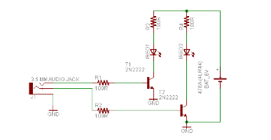
Sadly, there’re no pin markers on the mechanical endstop module I bought from an Indian online store. Next is the schematic of that mechanical endstop module drawn by me.
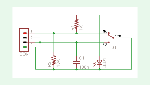
As can seen in the schematic, NC terminal of the micro switch (S1) is in fact the Vcc input (red), NO is the Gnd rail (black), and the COM is the signal output (green or the like). Here, resistor R1 (1K) serves as the current limiter resistor for the status indicator (LED1) while remaining components R2 (10K) & C1 (100n) are supporting components of the signal output (active-low) line.
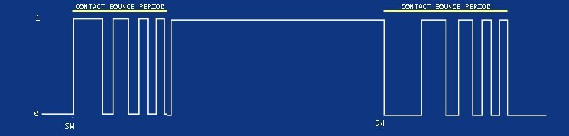
Perhaps it’s necessary, sometimes even important, to keep an eye on the actual performance of an endstop. Because it’s observed (by me and many others) that there’s not only significant bouncing while the mechanical switch is being operated but also some unwanted noise with high amplitudes. Switch contact bounce is a usual issue for all mechanical switches, occurs when the metal contacts of the mechanical switch are pressured together, the property of the metals used causes the contacts to bounce apart. How frequently the contacts bounce before the final latch depends on the contact type and ofcourse the property of the switch. The bouncing effect can causes multiple high frequency pulses, as opposed to a clean output transition, thus results in an undesired action especially if it’s linked with a microcontroller-based piece of circuitry. You can see a basic plot (for reference) below.
When it comes to the noise issues, it’s worthy to notice that in a 3D printer itself, there’re some substantial noise sources such as stepper motors and pulse width modulation drivers. Things will turn worse if the wires of the endstops are in the same cable where wires to stepper motors are!
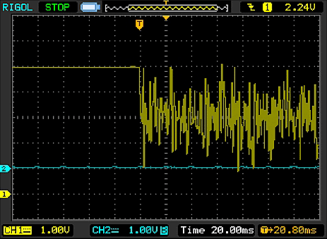
The following scope trace shows the moment when the stepper motor in a RepRap-based 3D printer, which shares the cable with probed endstop input is engaged. If you like to go farther in this matter, you see the story here https://wot.lv/combating-endstop-noise-on-a-reprap.html.
It’s time for me to document how I conduct a crude test of my mechanical endstop module just to see the performance of its electronics. I simply powered the module up with a bit noisy 5VDC power supply (it’s intentional) and probed my scope on the signal output (green) wire with respect to Gnd (black). Below you can find a casual scope trace of the output transition captured while releasing (after a depression) the little lever on the endstop. I don’t have a 3D printer yet, so I’ve never felt the need to test endstops in real world (donate one to me if you want me to! Ha Ha).
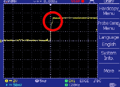
See the little time lag it took for signal to complete the shift after endstop was released, not a big concern, though.
In my view, mechanical endstops are good enough as it’s by far the most common and pretty cheap type when compared with the counterparts. But quite often it’d become essential to ‘clean’ the output signal perhaps by means of a noise filter mechanism – not a tedious task indeed.
Other Endstops
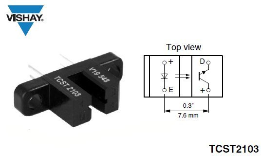
The second type of endstop is the optical endstop. An advantage of using optical endstops is that optical endstops can be activated without any physical contact between the carriage and the endstop. The key component in an optical end stop is a fork-type (u-shaped) opto-interrupter (photo-interrupter) device – usually a type TCST2103 from Vishay Semiconductors.
The TCST2103 is a transmissive sensor that includes an infrared emitter and phototransistor, located face-to-face on the optical axes in a leaded package which blocks visible light. Apart from the photo-interrupter, only two resistors are needed to build a complete optical endstop.
Next type of non-contact endstop is the Hall-Effect endstop that uses a Hall-Effect sensor, which is triggered in the close proximity of a magnetic field. When the carriage mounted with a permanent magnet nears the endstop, the Hall-Effect sensor detects the magnetic field and activates the endstop. The key component in a common Hall-Effect endstop is the A1302UA Hall-Effect sensor.
The A1302 (from Allegro MicroSystems) is a continuous-time ratiometric linear Hall-Effect Sensor IC, optimized to accurately provide a voltage output that is proportional to an applied magnetic field. These devices have a quiescent output voltage that is 50% of the supply voltage. Typical sensitivity of A1302 is 1.3 mV/G. The suffix UA denotes a 3-pin SIP package while suffix LH is for SOT23W. This simply means two device package types are available: LH, a 3-pin SOT23W type for surface mount, and UA, a 3-pin ultra-mini SIP for through-hole mount.
You can find much more information about Hall-Effect endstops (including schematics) here – https://reprap.org/wiki/Hall-Θ.
A search on the internet showed me that it’s rather difficult to manually position a mechanical endstop for the Z-axis with a narrow between the nozzle of the extruder and the surface of the heated print bed. However, a Hall-Effect endstop module (with a linear sensor, like the aforesaid one) will be a good fit in such a situation as it provides a variable sensitivity adjustment for the magnet through an onboard trimpot. Quite simple, but note that a Hall-Effect endstop module centered on a Hall-Effect Switch like the A3144 is not suitable for this trick as it can deliver a logic-high (H) or logic-low (L) output only!
Sum-up
At bottom, an endstop with an active-high output holds the signal pin at about 0V when the switch is not triggered, and about Vcc level when triggered. Likewise, an endstop with an active-low output holds the input pin at about Vcc level when the switch is not triggered, and about 0V when triggered.
And in my opinion, the most simple and cheap endstop to use is mechanical endstop. Anyway, you can easily and quickly adjust the distance of the printbed to the nozzle if you’ve a Hall-Effect endstop, its supporting circuitry is a bit complex, though. The problem that you may have with an optical endstop is the inadvertent false triggering induced by strong external light sources.
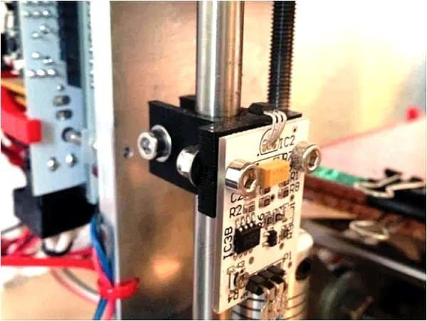
At last, because I already had a bunch of MH183 Hall-effect sensor switch ICs, I decided to start with making one simple Hall-Effect Endstop. And, I already constructed a working proof of concept breadboard model of the ‘digital endstop’ (see below schematic).
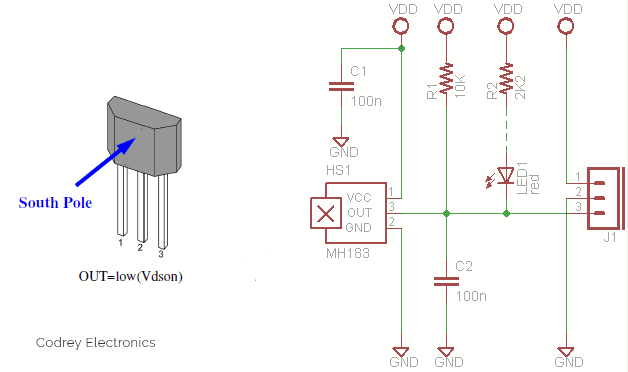
The schematic is extremely simple and straight forward as it’s centered around the MH183 which is a CMOS unipolar Hall-Effect Sensor IC. Note that its output transistor will be switched on (BOP) in the presence of a sufficiently strong South pole magnetic field facing the marked/ branded side of the package. Similarly, the output will be switched off (BRP) in the presence of a weaker South field and remain off with “0” field. Do not apply reverse voltage to the sensor, as it may be cause irreparable damage to the sensor. For reverse voltage protection, a 100Ω resistor in series with VDD (Pin 1) of MH183 is recommended. You can also try the good old A3144 Hall-Effect sensor as a drop-in replacement. Keep note, Allegro’s A3144 is a discontinued product, but still available through some online sellers. One recommended substitution is A1104.
Okay, I’ll test my build (through a borrowed 3D printer) up over the weekend. Let’s see how well it works!