This post shares the design idea of a simple and cheap door status display panel with tristate indicators. The tristate visual indication features three independent modes viz. steady red (busy indicator), steady green (free indicator), and flashing red-green (wait indicator).
The Door Status LED Indicator concept at this time is centered around a generally available CMOS Hex Schmitt Trigger Inverter chip CD40106B. Well, let us see how it goes…
Low Power Oscillator Backdrop
First off, recall various oscillator circuits we built earlier. Simply, an oscillator circuit changes values over time in a periodic manner.
When connecting a capacitor at the input of an inverter gate, discharging the capacitor will cause the output of the inverter gate to be near the positive rail voltage (V+/VDD), whereas charging the capacitor causes the output of the inverter gate to be near the ground rail voltage (0V/GND).
So, inserting a resistor between the output and the input of the inverter gate where the aforesaid capacitor sits, the output of the inverter gate does the job of both charging and discharging the capacitor, thus forming an astable oscillator.
The CD40106B Schmitt Trigger Inverter TI datasheet depicts a form of memory – hysteresis – within the device where the input/output relationship for changing input values will depend on the time history of the input.
For instance, if the input voltage VIN starts at 0V/GND and climbs up, the output voltage VOUT will remain High until the input voltage reaches the value VP as demonstrated in the below transfer characteristics figure.
At this point, the output voltage will drop to 0V/GND. As the input voltage then drops off below VP the output voltage persists in resting Low until finally the input falls below a value of VN.

Put differently, the input threshold voltage of a Schmitt-trigger inverter changes depending on the output state of the gate. That is, in the case of a Schmitt-trigger the input threshold level receives a small positive feedback from the output. Hence when the output is triggered High, the input threshold voltage is boosted a small amount. Similarly, when the output is Low the input threshold voltage is lowered a small amount. This positive feedback of the output to the input is referred to as hysteresis.
Note at this point that VN and VP are the two input threshold levels, where VP is the input threshold required for the output to transit from High to Low.
Door Status LED Indicator DIY
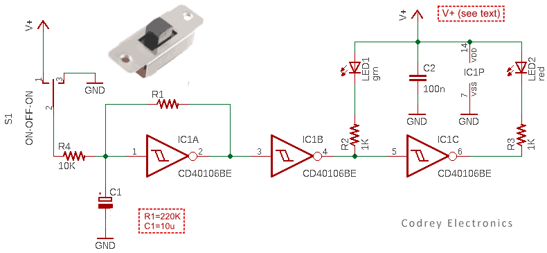
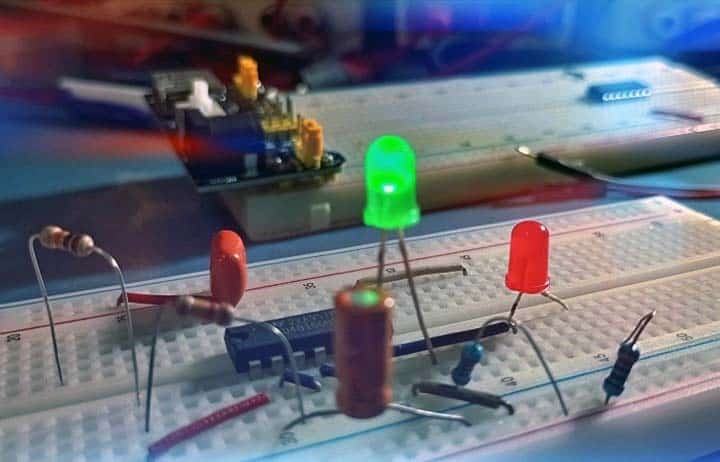
As can be seen in the above schematic, first gate (IC1A) of the CD40106BE (IC1) is configured as the free-running oscillator. The oscillator frequency is determined by RC components R1 and C1. Next two gates of IC1 (IC1B and IC1C) are used to drive the green and red lamps (LED1 and LED2). The 1KΩ resistors R2 and R3 works as current limiting resistors.
The power supply (V+) can be any DC voltage between the minimum and maximum supply voltage rating pointed in the datasheet but the recommended range for the current scheme is 3V to 5V. The 100nF bypass capacitor (C2) is there to prevent power interferences, so it must be kept as close as possible to IC1’s power pins (IC1P) for best results.
The mode selector switch (S1) plays a significant role here. As you might already noticed, it is a simple ON-OFF-ON slide switch also known as “Centre OFF” slide switch. The modes are as follows:
- S1 – Position 1 (Left): Red LED2 Steady ON
- S1 – Position 3 (Right): Green LED1 Steady ON
- S1 – Position 2 (Centre): Red & Green LED ON (Flashing)
Needless to say, since the CD40106B chip has six independent inverter gates, you can easily exploit the next three gates to build a second channel of the door status indicator (perhaps with a bit different circuit components and configuration).
At the time you are doing further circuit/design modifications, however, keep an eye on the maximum sink/source current ratings of the inverter gates to ensure maximum safety and reliability.
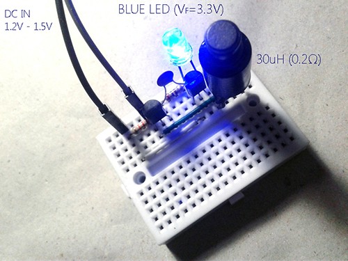
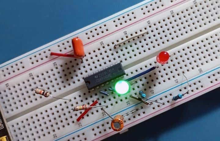
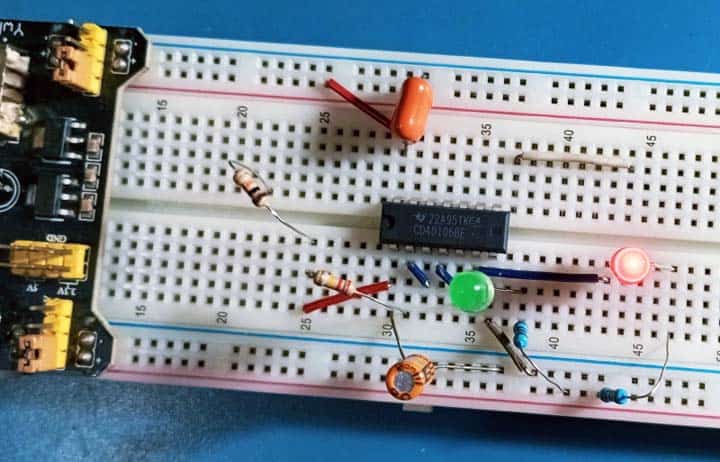
As an aside, about a year ago I bought some 3-way slide switches to build a motorized toy, but you cannot see it in my quick test circuit I made on the breadboard (5VDC). For the tests, I used a pair of breadboard jumper wires for the mode selection because I could not find the slide switch packets in the pile of junk (trust me my breadboard setup worked as expected).
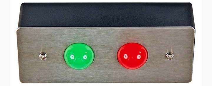
I will not go into the details of making the enclosure because it is (hopefully) easy for you. Anyway, another borrowed concept is shown below.
Conclusion
That is all for now. Once you get the hang of it, it is a very straightforward and relatively simple do-it-yourself project. Good luck with yours!