Now get ready to make your own safe car power socket using inexpensive components that are generally available. The simple device can then be used as a safe accessory power outlet to extend the 12VDC supply coming from the car cigarette lighter socket!
So, it is now easy to power anything with the same power socket that was used only as a car cigarette lighter socket (https://en.wikipedia.org/wiki/Automobile_auxiliary_power_outlet) until now.
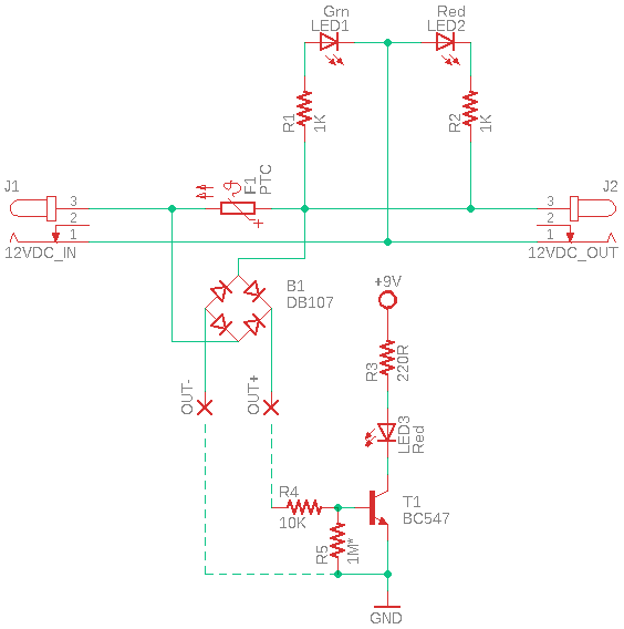
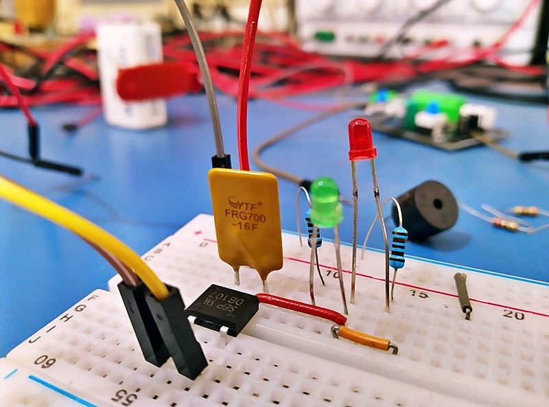
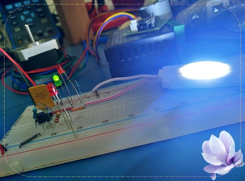
The circuit in below figure is a safe car power socket designed around a few discrete components, all of which you can probably find in your junk box. The PTC resettable fuse, F1, is really the heart of this circuit. My breadboard prototype, which matches the diagram below, was tested with an FRG700-16F PTC fuse (7A/16V) as that was all I had on hand at the time.
Now onto a few design details you might want to know…
Referring to the schematic provided, J1 is the DC12V input socket and J2 is the fuse-protected DC12V output socket. Green LED1 acts as a correct polarity (tip positive, sleeve ground barrel power jack) indicator, while red LED2 is included to indicate wrong/reverse polarity input. The resettable PTC fuse (F1) is inserted on the default positive rail and hopefully needs no further explanation.
One thing lurks in this little design is the use of a DB107 bridge rectifier (B1). See, it works as a crude blown-fuse indicator that allows you to monitor the fuse status even remotely. That means, when the resettable fuse breaks the power supply path for any reason the output of the bridge rectifier provides a DC voltage (OUT+ and OUT-) which can be further processed by an external analog or digital circuit.
As an example, you can see an optional 9V battery powered remote blown fuse indicator circuit at the bottom of the schematic. It only demands a BC547 transistor (T1) and a few other simple components to make it. Note that you can also set up a small microcontroller to monitor the fuse status, but just be careful to remove the blown fuse indicator LED and employ an appropriate optocoupler there.
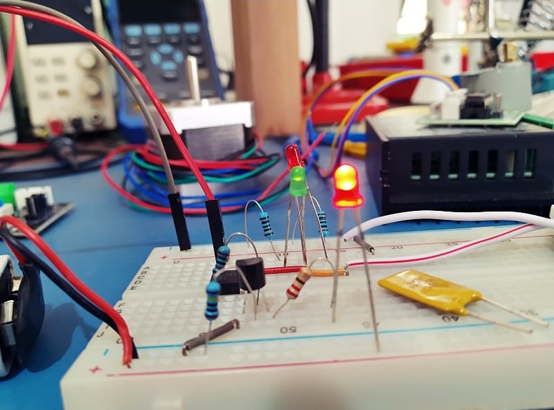
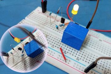
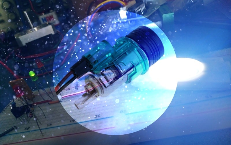
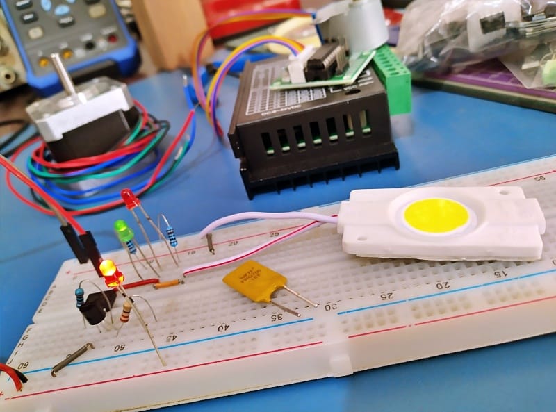
For some quick workbench tests, I assembled the entire system on a breadboard with a 12VDC medium-power white LED as the output load, and it worked as expected.
Jumping to the quick conclusion, I agree that this is not a full-blown design, as it was prepared only with the intention of giving a spark of an idea to beginners and hobbyists. But if you have a bit of skill and patience it can definitely be shaped into an end-user product. I leave that to you…
Also, take a close look at this concept and let me know in the comments if you notice any discrepancies results primarily from things that I may have overlooked during the design process. See you next week. Have Fun!