Nowadays, there are various types of switches available to help you track whether your door is open or closed. Such a door status monitor switch changes its states when the door is opened or closed. Typically, this is accomplished using a magnetic reed switch that is surface-mounted on the edge of the door and door frame.
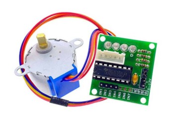
The most common example of a magnetic door status monitor switch widely used by electronics hobbyists and makers is the relatively cheap MC-38 Door/Window Magnetic Sensor Switch (see below).

Here are its quick specifications taken from a Chinese datasheet:
- Rated Current: 100mA
- Rated Voltage: 200VDC
- Operating Distance: More than 15mm (< 25mm)
- Rated Power: 3W
- Output: NC (normally closed)
The reed switch part of MC-38 is typically installed on the door frame and the magnet part that activates the reed switch is typically mounted on the door. Note that MC-38 is usually in closed state (when reed switch and magnet are close together) but if the door is opened, the magnet is taken away from the reed switch and shifts its state. The reed switch is non polar so we can plug in the wires in any way.
Well, the MC-38 is a quite popular “normally-closed” wired magnetic door sensor switch. But this is an issue in certain cases as we often need a “normally-open” switch to work with some homemade analog alarm panels or similar devices used to notify that a door is open. So I decided to ‘spruce’ it up a bit with analog electronics and design of that adapter is the prime theme of this little post!
You will need a few things to build this out, which are…
- 8050C NPN Transistor x1
- 1N4007 Diode x1
- 3mm Red LED x1
- JQC-SFC(T73)DC09V Relay x1
- SPDT Slide Switch x1
- 22KΩ ¼ w Resistor x1
- 4K7Ω ¼ w Resistor x1
- 470uF/16V Electrolytic Capacitor x1
- 6F22 9V Battery x1
Next you will need to connect the components as shown in the below schematic.
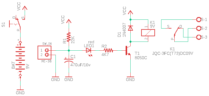
Having got everything wired together, connect the MC-38 door switch to the input points (SW_IN) of the setup. As delivered, the door switch comes with bare wires – you could solder them directly to the input points, but for a more reclaimable solution it is better to use appropriate wire connectors.
Well, you are now able to monitor whether or not the door is open and wire the relay’s “normally-open” switching contacts (S-1 and S-2 in the schematic) to fire an external alarm or lamp to raise a perceptible intrusion alert when the door is opened by someone.
This circuit is in fact a 9V battery operated single transistor relay driver with a simple turn-on delay feature. You do not need to do anything particularly special when setting up the circuit – I just assembled it on a breadboard to do some quick tests (see below).

However, the relay needs some special attention as it should be a low-current type 9V relay. Below you can see the quick specifications of the JQC-SFC(T73)DC09V PCB relay I used in my prototype.
- Nominal Coil Voltage: 9VDC
- Coil Resistance: 225Ω ±10%
- Operate Voltage: 6.8VDC
- Release Voltage: 0.9VDC
Nevertheless, this pretty simple circuit may also be helpful to learn some basic electronics. It only contains a handful of inexpensive electronics components. Since it uses an R-C setup to turn the relay on with a little delay, the time lag (~4s default) can be adjusted by changing the value of the electrolytic capacitor C1.

Future steps are up to you! That is where my post ends, but hopefully it outlines the build ideas for more interesting things you might create. Simply, with the status of the door known announced by hardware, you could report it to the brain of an intrusion detection annunciator/burglar alarm system or to the GPIO of your favourite microcontroller…
Hopefully you found this a fun use of some simple discrete components. If you enjoyed this post, please share it far and wide.