I think you’re all familiar with the various Chinese sensor modules based on the LM393 IC. That’s good, but at this point I’ll share the design idea of an LM358 IC based variable threshold solid state switch. This is actually an adaptable design of a galvanically-isolated dual channel solid-state switch which can work with almost all discrete analog sensors. So, let’s jump in!
Right now, you’ve access to millions of operational amplifiers (op-amps) on the market. There’re several different varieties, each with its own unique features.
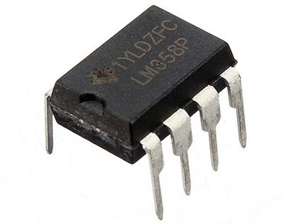
Coming to my choice, the LM358 IC consists of two independent, high gain, internally frequency compensated op-amps tailored specifically to operate from a single power supply over a wide range of voltages.
Not to mention, using a LM358 IC, we can easily setup an elementary comparator with hysteresis. At this point, keep note that an op-amp generally does not make a good comparator. However, there’ reasons to occasionally use an op-amp as a comparator. These include having no timing requirements, having inputs that exceed Vcc, etc.
So, the following is the tried and tested circuit diagram of the proposed variable threshold solid-state switch that uses only a single op-amp of the long-lived LM358 IC (the second op-amp is not used and wired ultimately as a voltage follower, but not shown here).
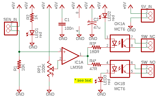
The universal sensor input of the circuit is arranged in a voltage divider with the external analog sensor – a photoresistor, for example. Since the op-amp is wired as a comparator, its output is either LOW or HIGH. The non-inverting input of the op-amp sees the output of the divider, which is a voltage that varies with the status of the external analog sensor. At zero voltage input, the output of the op-amp will be LOW, but when voltage at the non-inverting input of the op-amp exceeds the voltage of the inverting input, the output of the op-amp will toggle HIGH. The triggering voltage, and therefore the sensor threshold, can be varied at the inverting input by the multiturn trimpot. Note that the variable threshold set trimpot can be replaced by two fixed value resistors in a voltage divider configuration.
Likewise, a hysteresis resistor can be employed in this circuit as a debouncer to eradicate multiple triggering of the output that might occur at times. Hysteresis is reliable and can be applied predictably using small amounts of positive feedback.
Regular visitors of this site will no doubt guess where this session is heading! A comparator is used to differentiate between two different signal levels. Noise (or signal variation) at the comparison threshold will cause multiple transitions. Since hysteresis sets an upper and lower threshold, it helps to wipe out the multiple transitions caused by noise.
Recall, in our simple supply comparator scheme, the external sensor signal is fed to the non-inverting input of the comparator. So, you should apply “noninverting hysteresis” to get rid of instabilities due to noise. Read more https://www.ti.com/lit/ug/tidu020a/tidu020a.pdf
A solid state switch is a completely electronic device with no moving/mechanical parts as semiconductors provide the switching states. As you can see, the dual channel solid state switch at the output of the comparator is based on the easily accessible two-channel optocoupler MCT6.
The LM358 IC’s internal push-pull output circuitry makes the intended dual-channel switch configuration pretty easy!
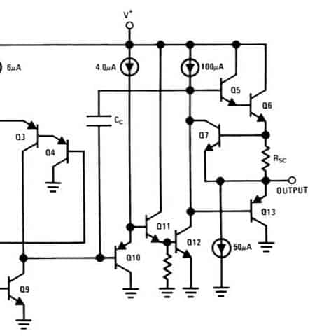
At this point, note that LM358 can provide a LOW output voltage near the ground rail (GND/0V), but the HIGH output voltage is significantly lower than the Vcc power rail (~Vcc-1.5V). You should take this into account when choosing current limiting resistors (R3-R4) for your optocoupler.
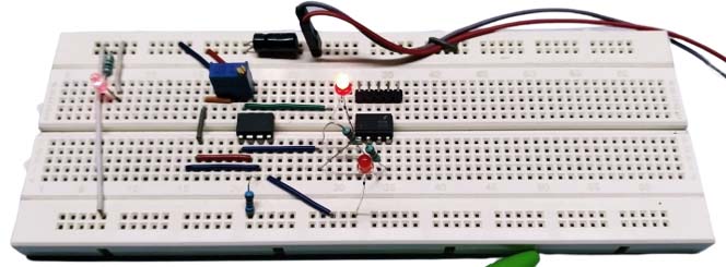
Below is a picture of my crude prototype made on a standard breadboard. However, it worked well with common analog sensors such as photoresistors, thermistors, varactors, etc. That’s it for now!
Jumping to a quick conclusion, I’ve used old school electronics tricks like this in the days when a microcontroller represents a significant cost, and it’s still a pleasure to fiddle with those cute analog ideas. There’re still lots of analog electronics tricks left to talk about in future articles!
Have you forgotten the great art of soldering in the world of cheapo Chinese sensor modules? Time to refresh your soldering skills.