As mentioned in my previous post, some analog multimeters offer the hFE test feature via a custom-made hFE connector that is usually sold as an optional accessory.
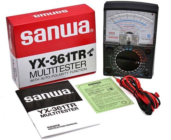
The popular Sanwa YX-361TR analog multimeter is a good example of this case.
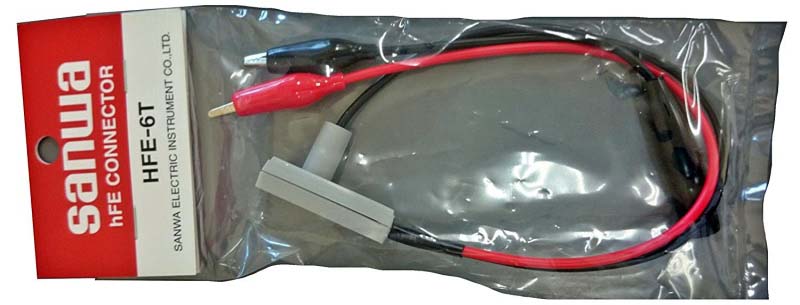
Below you can see its $22 hFE connector with the model number HFE-6T.
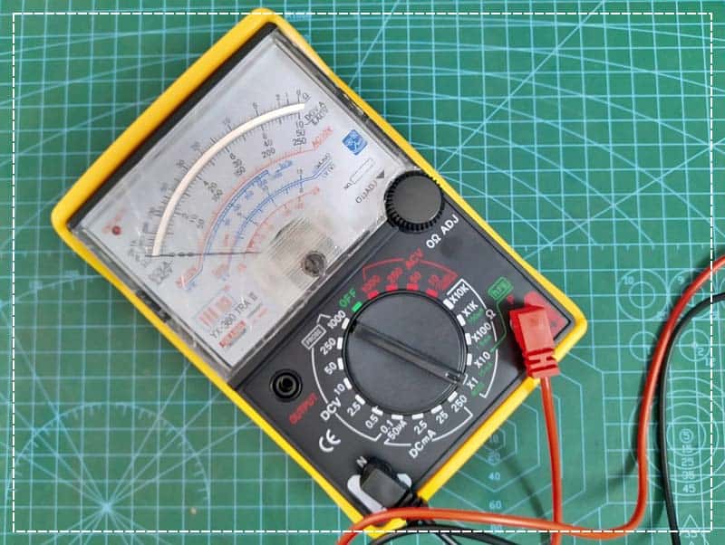
The analog multimeter (VAR TECH YX-360 TRA II) I recently bought has a similar hFE connector, but I do not have it with me. So, I made a standalone one to use with it (that is the story of the aforesaid post). Anyway, a few days later I followed the idea of that Sanwa accessory and made another hFE connector for my multimeter. It is certainly not a reliable add-on but it will serve as a useful thing for quick go/no-go tests. So, this post is about that little attempt…
This is the schematic of the add-on hFE connector/adapter tailored for the YX-360 TRA II analog multimeter.
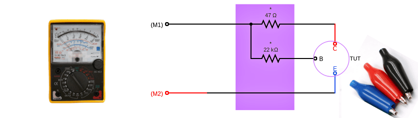
Since this setup uses the resistance measuring range to measure hFE, remember to make full scale adjustment (OΩ ADJ) of the meter needle before doing the measurement. Just as before measuring resistance, turn the range to x10Ω, short circuit the + and –COM terminals and align the needle to 0Ω line with 0Ω ADJ knob.
Then depending on the polarity of the transistor to be tested (TUT), insert the first input lead (M1) of the hFE connector into the -COM socket (black) of the meter if it is NPN transistor and into the + socket (red) of the meter if it is PNP transistor.
As you can see, the hFE connector has three test lead lines each with an alligator clip at the end. Connect the black clip (B) to the base terminal of the transistor and the red clip (C) to the collector terminal.
Then connect the third/blue clip (E) to the emitter terminal of the transistor under test, and plug the second input lead of the connector (M2) to + socket of the meter if the transistor is NPN and –COM if PNP. With this connection, the multimeter needle responds, indicating the lC/lB (hFE) value on its blue hFE scale.
Note at this point that this is not a true hFE measurement adapter but you can use it to calculate approximate hFE value for quick diagnosis, pair matching etc. You may also need to change the values of the 47Ω and 22KΩ resistors to get more sensible results. That is it!
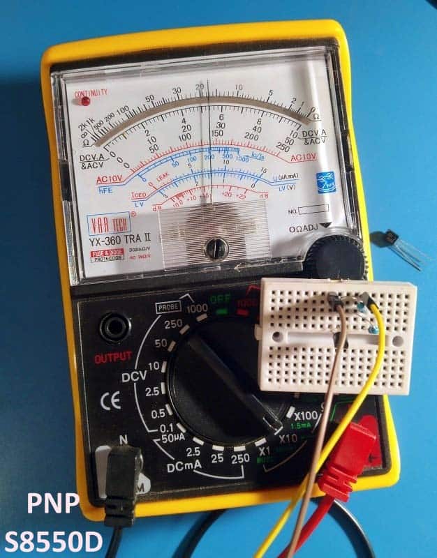
I built my quick prototype on a mini breadboard and used NPN transistor 8050C and PNP transistor S8550D for the first quick tests. The results were pleasing and fairly close to the findings of my digital transistor tester.
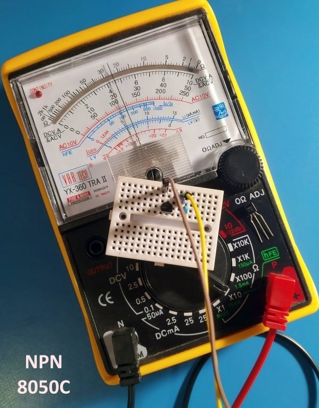
Other NPN/PNP transistors that have been successfully tested later include BC547, BC557, CL100,CK100 etc.
However, I saw a noticeable drift (circa 30% less than awaited) in the hFE value of the PNP transistor but I know that is due to my compromised biasing scheme (improvement ideas are welcome).
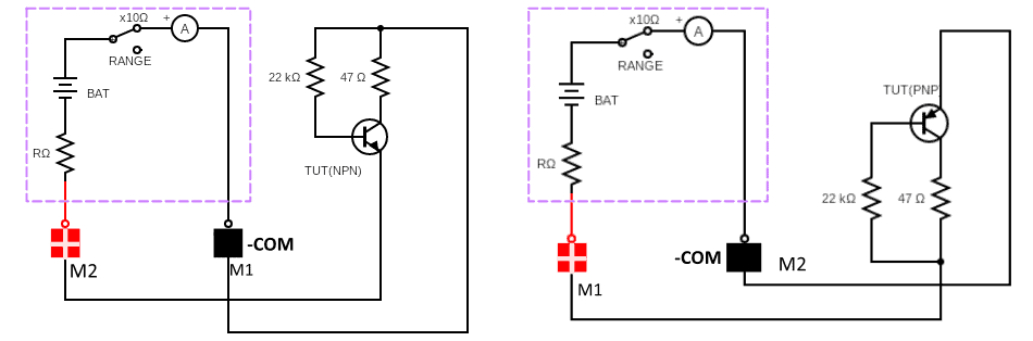
Well, the figure below roughly exemplifies what happens in the background when testing NPN and PNP transistors with my hFE connector/adapter.
Finally, this hFE connector is pretty helpful for comparing transistors for sorting (matching) purposes. But although the test is very easy and fast, some issues of the transistor under test cannot be known by this simple approach. Moreover, while on the surface this concept may seem simple to implement, in practice it is not as easy as it sounds.
In another post, we will learn how to use an oscilloscope and a function/arbitrary waveform generator for more substantial transistor exploration. Keep on learning…