The hFE socket on most cheap digital multimeters provides a dc gain value (often simply pointed as β) useful for evaluating small signal silicon transistors. However, only a few multimeters with the quick NPN/PNP transistor test function delineate the test conditions while many others remain silent about it. Note that since the test current is obscure, the hFE reading itself needs to be counted very approximative. Anyway it is often practicable for intents like quick testing, diagnosing, sorting, matching, etc.
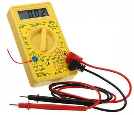
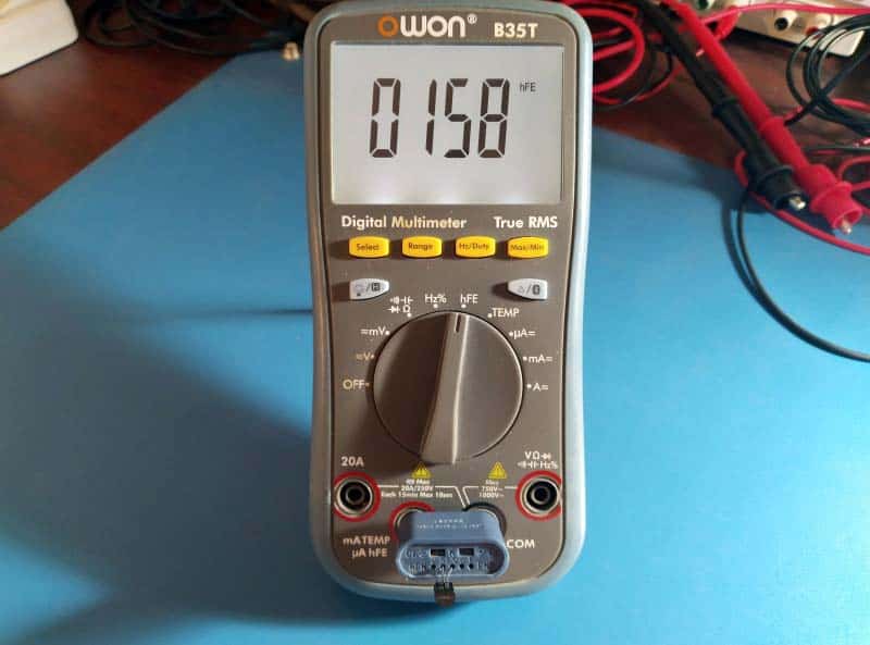
Interestingly, my high-end handheld digital multimeter does not have a dedicated hFE socket (but it comes with a removable adapter for testing and measuring semiconductors). And as you noticed, most benchtop digital multimeters do not include such a devoted panel socket to measure hFE as it invalidates certain safety considerations.
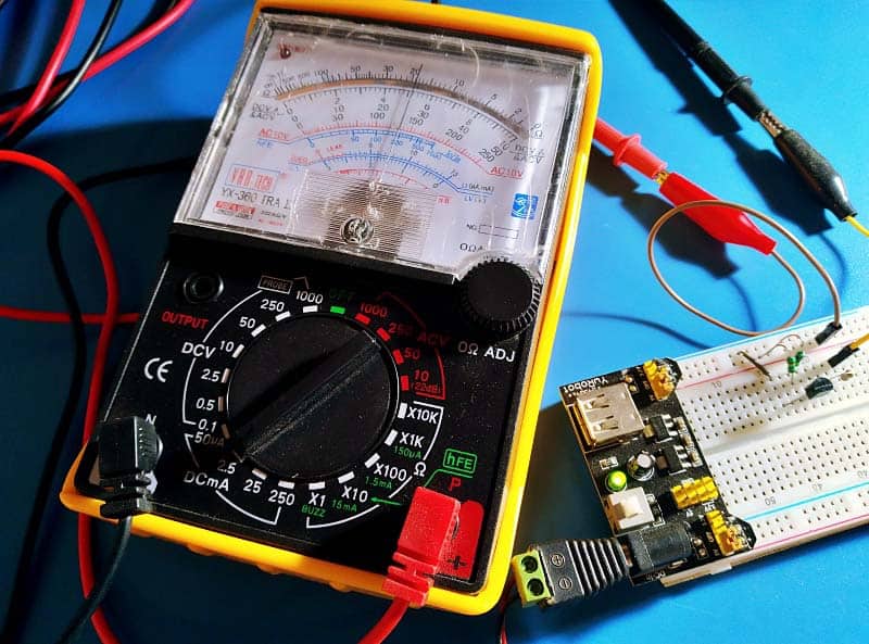
Very recently I bought another analog multimeter (VAR TECH YX-360 TRA II) on a whim.
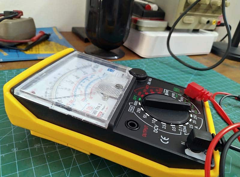
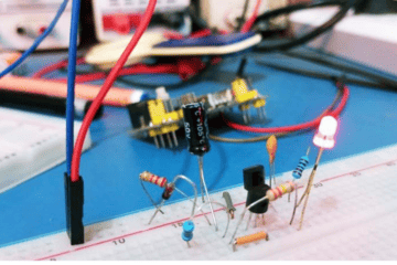
Upon closer inspection, it was discovered that the analog multimeter also offers a transistor hFE test function but it demands an optional adapter that needs to be purchased separately (see below). Since the custom-made adapter was a bit difficult to purchase locally and lacked useful documentation, I decided to make a standalone one. So, what follows is a crude breadboard circuit I built to measure hFE with my new analog multimeter.
Now recall that hFE stands for “Hybrid parameter forward current gain, common emitter” which is a measure of the DC current gain (β) of a bipolar junction transistor (BJT).
Here in my case, the analog multimeter is set to measure the collector current of the transistor under test while its base gets nearly 10μA of current. The hFE value then is the resulting mA value x100. For example, if the multimeter reads 1mA, 100 is the hFE of the transistor under test!
While measuring NPN transistors, the setup should be wired as shown in the below diagram. For PNP transistors the power source and the multimeter probes should be reversed as well since you are using an analog multimeter (in case of a digital multimeter it does not matter which test probe goes where). Nevertheless, you can add a regular DPDT slide/toggle switch (or a pair of suitable test sockets) to this basic setup to easily swap between NPN and PNP transistors. There is no need for a power on/off switch, with empty test sockets no current will flow.
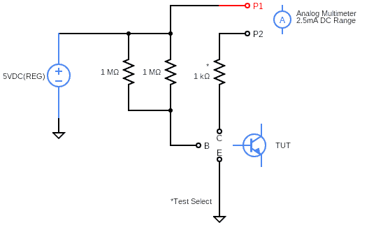
So, connect the analog multimeter probes to P1 and P2 respecting polarities, configure the setup depending on transistor type (NPN/PNP), then insert the transistor in the test socket and read the hFE value on the multimeter display. That is it.
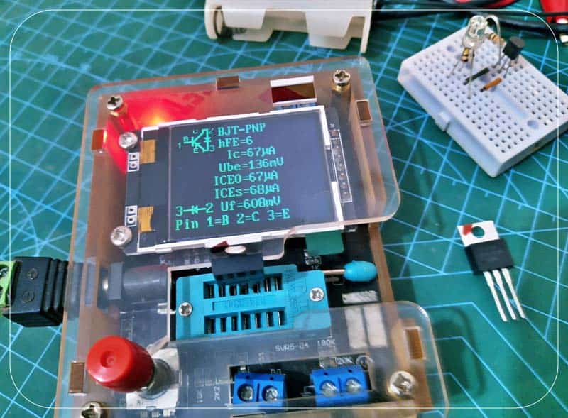
By using some jellybean small signal transistors I was able to test this concept successfully. Now see my quick and dirty breadboard setup (powered by a regulated breadboard power supply module) with a randomly picked NPN BJT (S8050) under test!
At that time the analog multimeter indicated a collector current of about 1.4mA, so calculating the hFE value of S8050 returns 1.4 x 100 = 140. It does not matter much but the hFE value is fairly close to what my digital multimeter’s transistor tester displayed (see below).
Even if the obtained value is not a true hFE, this poor man’s test procedure can be used to verify transistor gain, grade unknown transistors, and match paired devices for use in peculiar applications like current mirrors, for example.
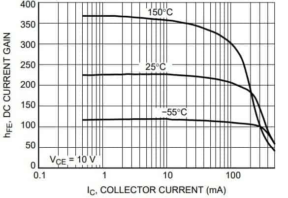
The hFE parameter value on the other hand is a bit fretful. Look, our hFE calculations are typically based on the textbook notion hFE = IC/IB, yet transistor datasheets offer a range of values for hFE under various collector current conditions (see a sample snip below). Besides, manufacturer test conditions also use a brief pulse mode where the transistor under test is active for a pretty short duration (more on this later).
Finally, I know this is not the best way of doing this but for basic tests this poor man’s version runs pretty well. A future post will definitely delve a bit deeper into this topic, and you can see random thoughts on fancy semiconductor testers, curve tracers, etc. in the forthcoming post. See you then!