This post explains how to build a Hyper LED Switch using a set of simple and inexpensive electronics components that are available everywhere, you can even find them in your junk box.
So, what is the Hyper LED Switch? It is actually nothing but a battery-powered ultrasensitive LED switching circuit centered around two BJTs (Bipolar Junction Transistors). But do not underrate this analog concept just because it is simple, you will realize later that it can actually be used in many different applications.
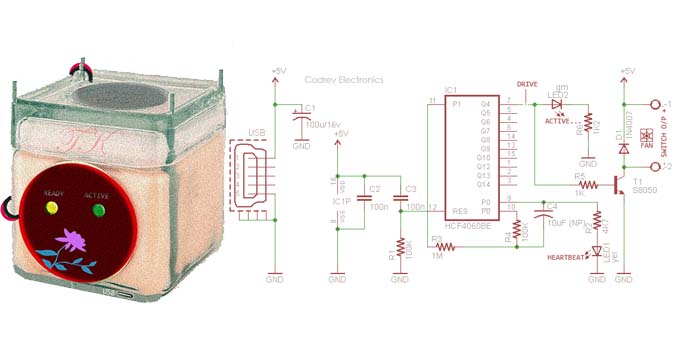
Below you will see its basic schematic diagram. Although the circuit is splendidly simple and self-explanatory, I am giving some significant notes about it after that.
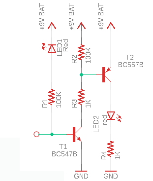
As can be seen in this schematic, there are two 5mm water-clear red LEDs (LED1-LED2) along with two small signal transistors BC547B and BC557B (T1-T2). A 6F22 9V battery is recommended as the power source for this setup.
The first light emitting diode (LED1) serves as a reverse-biased photodiode. In the idle state, both transistors are de-energized and the overall current consumption is negligible. A flash of light from a fairly close distance is enough to switch on the second light emitting diode (LED2) which roughly serves as a visual indicator. Alternatively, you can tap the base leg of the first transistor (T1) with your finger to wake the system up.
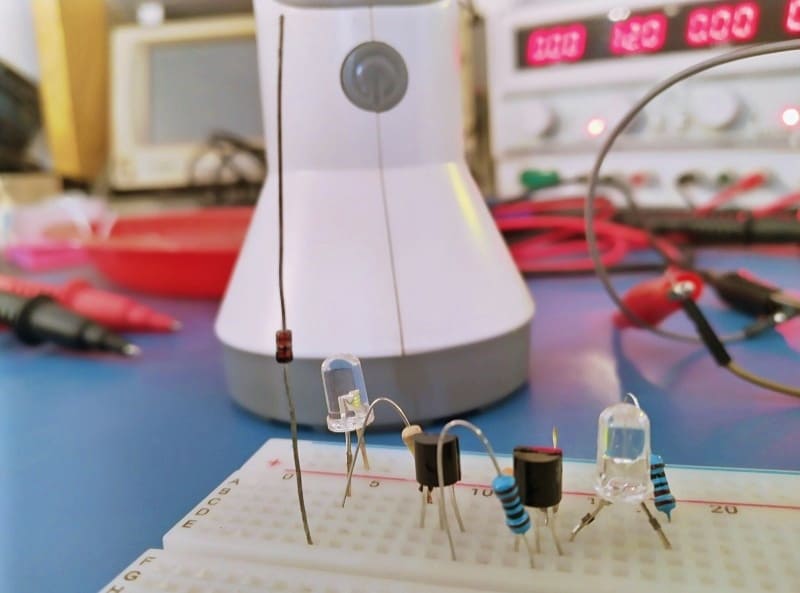
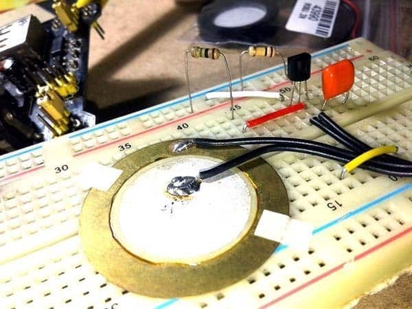
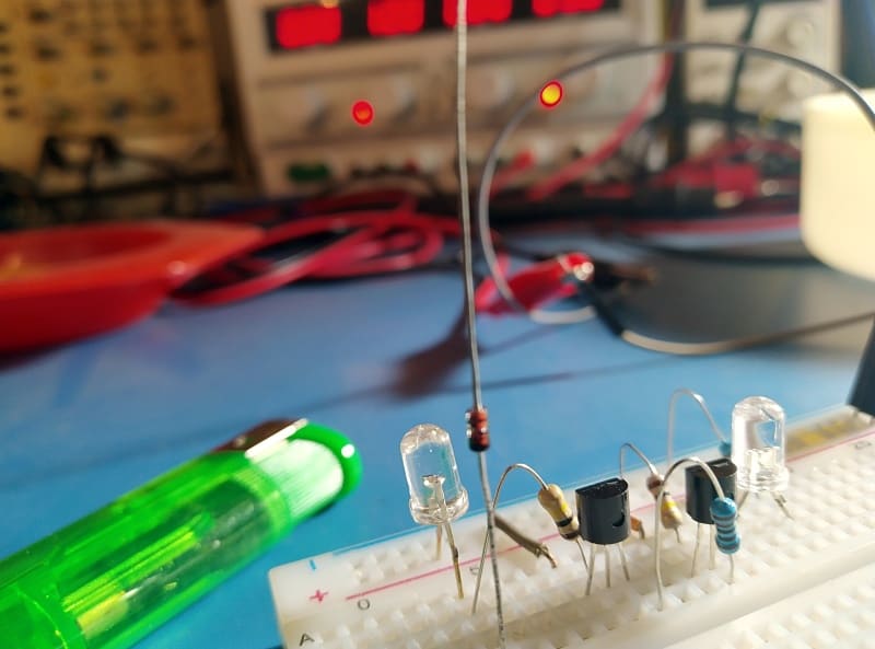
It might be a bit of a surprise to see the pictures of my test setup wired up on the breadboard, as it also has an unmentioned diode sticking up in free air!
Oh, I am coming to it… After some testing, I added a 1N4148 small signal silicon diode (D1) as a gimmick antenna to my original setup. The updated schematic is given below. This diode antenna is not very necessary here, as a bit of bare copper wire is adequate for it. But for some reason I still insist on the use of that diode.
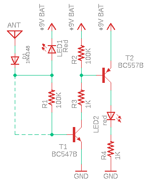
The 1N4148 diode can be wired as shown in the schematic or connected directly to the base leg of BC547B transistor as indicated by the dotted line. Either way, this does not significantly affect the light sensing feature of the circuit.
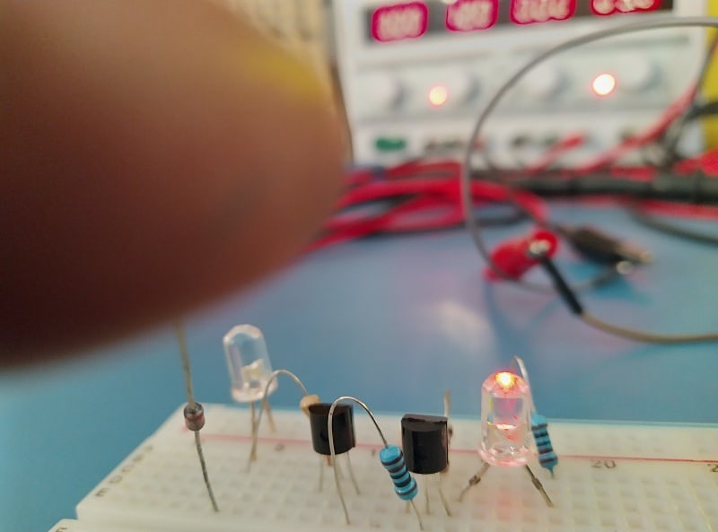
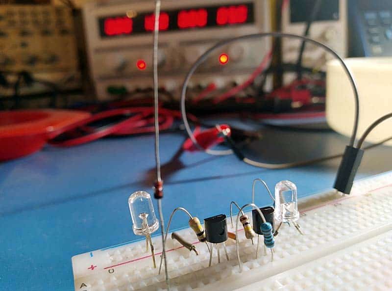
From now on you can touch the antenna (loose end of the diode) and/or activate it with an electric impulse generated by a nearby cigar lighter or gas lighter to get a fairish glow on the LED. Moreover, you can also switch a device on the mains to generate ample interference pulses to trigger it. This works better if you have a bit lengthier antenna.
I used an aged very poor quality 6F22 9V battery for the tests. During tests conducted in-lab I was able to keep the prototype continuously in standby state with the occasional triggers for more than 14 days without any problem (at least in my case).

OK, now you have an ultrasensitive LED switching circuit. It is composed of a standard light emitting diode as the light sensing part and a small signal silicon diode as an antenna for capturing touch signals and electrical impulses. The output voltage of the circuit available across the final LED is however a transient signal, but you can make it steady with a simple external timer (or latch) circuit.
If I have some time in the future, I might improve this little concept to create something more fantastic like a camera slave flash trigger or a lightning detector or a static electricity sensor. And the rest you can experiment…