There are a lot of different parts in the electronics world, and often parts with the same functionality come indifferent forms and sizes. Now it is the time to pick another cheapo microwave motion sensor doppler radar module to build a universal radar motion detector switch. Okay, this post goes over how to make it using the HFS-DC06 5.8GHz microwave radar sensor module!
So, this project centres around the 5.8GHz microwave radar sensor module HFS-DC06 which senses movements within a defined distance (detection sensitivity is adjustable with an onboard trimpot) and in response to detecting a motion it outputs a TTL pulse for a while (output retention is configurable with another onboard trimpot).
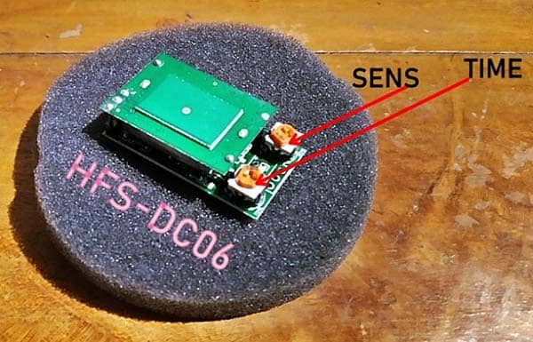
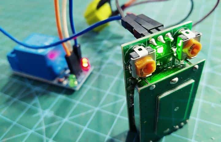
The sensing distance of this compact radar module is about 12 meters and it has a 360° sensing angle. The SENS trimpot allows you to adjust the distance from 0.5 to 12 meters, while the TIME trimpot allows you to adjust the output signal retention from 2 to 120 seconds. A green LED is also included in the module, which lights up when the output is active (TTL-HIGH).
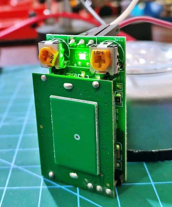
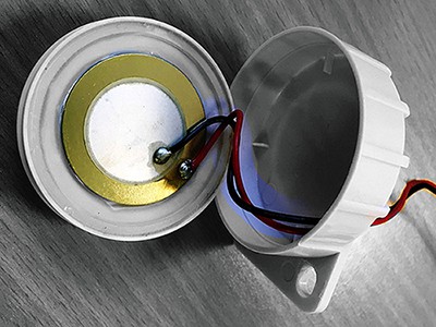
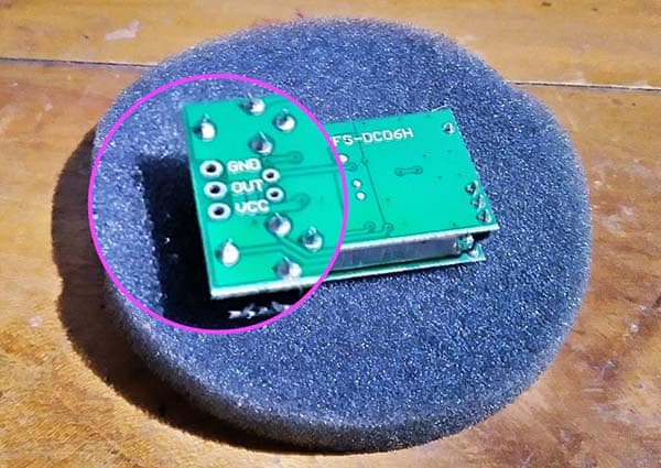
As you can see, the radar antenna is built into the front PCB of the module. The back side of the module reveals the simple interface: GND (0V), OUT (TTL LOW/HIGH), and VCC (5V). This module requires a regulated 5VDC power supply, and its minimum power consumption is around 30mA.
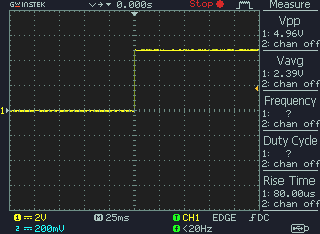
Below is an oscilloscope capture of the output signal (OUT) the module generates when it detects a valid motion.
I wanted to design the universal radar motion detector switch to be extremely simple and easy to elaborate. Frankly, my aim is to create a baseline or a little more than a proof of concept for how to create a compact movement detection system that can detect the change of speed of humans (and animals). The below shown rough scheme is pretty straightforward it is not worth going over in detail.
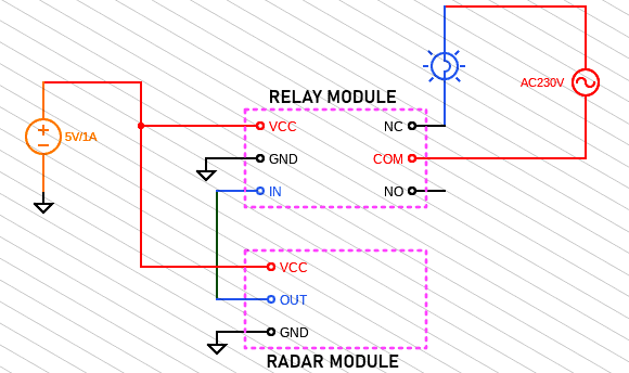
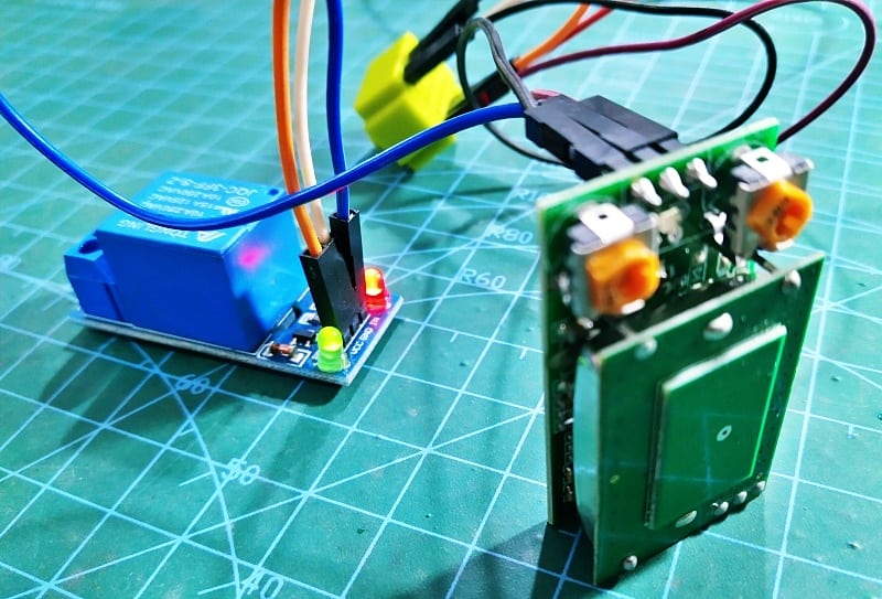
At this time, the output of the radar module is connected to the input of a 5VDC “active low trigger” relay module. And the whole setup gets power from a USB power supply (5V/1A). Note that the radar module’s output pin (OUT) is actually an I/O of its internal microcontroller, so it does not provide enough current to directly drive an electromagnetic relay or the like.
Also, normally the output of the radar module is low (L/0V) but changes to high (H/5V) when a movement is detected. Therefore, the relay module used here is normally in the energized state, but the external load connected through its common (COM) and normally-closed (NC) contact remains in the off state until motion is detected by the radar module.
I did it this way on purpose because the connected load (light or alarm) will turn on instantly to raise an alert when the power supply to the universal radar motion detector is interrupted (naturally or intentionally by someone). Obviously, you can use a 5VDC “active high trigger” relay module, but remember to change the output load wiring accordingly.
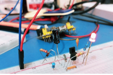
Following is a couple of random snaps of my initial test setup. And I ended with a working quick and dirty prototype!
OK, that is all about the build idea. Because this appears like a perfect candidate for simple home automation projects it should be very easy to convert this into an internet connected 360° motion detector without messing up with fatal mains voltage. If I am going to do that, I will share the design details here. You need to have a good reason to do so. Have you?