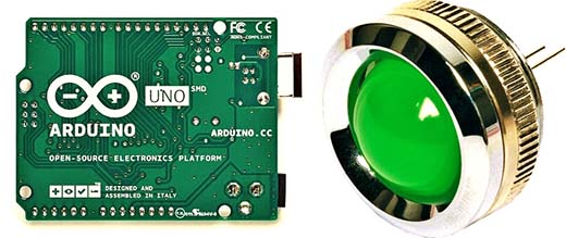
Arduino provides a number of analog inputs which enables us to measure parameters such as voltage, current, resistance, light, temperature, and so on in the analog arena. In this post, we’ll look at how to connect an analog sensor through the analog input of an Arduino, and how to render the final output in a simplistic fashion. The little experiment at this time can be easily executed on an Arduino Uno or a compatible board.

Arduino Analog – Quick Revision
Now recall that the analogRead() function is usually used to read an analog value via one of the analog input pins of the Arduino board.
And, in order to measure an analog value, there has to be a voltage level to compare it with. This voltage is called the analog reference (AREF). Needless to say, the voltages are always measured relative to the ground (GND) rail.
The Arduino has three analog reference voltage options – Avcc, the internal 1.1V reference, and the external reference.
An important note! When using the external reference voltage, you must set the analog reference to “external” before using analogRead() in the Arduino Sketch.
- The AVcc is the default reference voltage.
- The internal 1.1V reference can be utilized for absolute measurements of external voltages. This reference is more stable and hardly depends on the operating voltage or temperature.
- The external reference allows us to feed a reference voltage from an external power source. For example, if we want to measure voltages with a maximum range of 3V, we would feed a stable and smooth 3VDC into the AREF pin.
- It’s advised that the external reference voltage source should be connected through a 5KΩ resistor.
Arduino Uno has an ADC (analog to digital converter) with a 10-bit resolution (210). So, the value returned from analogRead() would be between 0 and 1023, where 0 represents 0V and 1023 represents the “real” operating voltage of the microcontroller in use.
And when it comes to the real operating voltage – it’s the regulated dc voltage feed to the core of the Arduino Uno board – the AVR microcontroller – which is 5V on paper.
Now note that when an Arduino Uno takes an analog reading, it compares the analog voltage at the analog input pin being used against the analog reference voltage. And, since the default analog reference voltage is the operating voltage, each unit returned by analogRead() is assessed in 5V/1024 = 0.00488V or 4.88mV.
See, this is very significant because the accuracy of the analogRead() values will be enormously affected by not having a precise operating voltage. That means, since the analog input voltage measurements are made relative to the reference voltage, fluctuations of the operating voltage (default reference voltage) undoubtedly influence the final outcome. For example, if the real operating voltage is only 4.8V, then the analogRead() scale of 0 to 1023 pertains to 0V to 4.8V (Not from 0V to 5V) which might not be trivial in most situations!

Arduino Analog – Read & Display
Well, get ready to read and display something, no matter what!
This session teaches how you can use an analog input of the Arduino Uno microcontroller to read an analog sensor. Here, as an example, a number of LEDs will be controlled by an analog input signal. In this experiment, we will use a couple of LEDs to represent the analog input signal. The higher the input signal level is, the more LEDs will light up, and vice versa.
Some utile things to keep in mind at this time:
- Arduino UNO has six analog input pins. These pins, configured as analog inputs by default, can be accessed via the names A0-A5. However, they can also be configured as discrete inputs or outputs.
- The analogRead() function reads the voltage value at the specified analog input. The input voltage ranges from 0 to the level of the reference voltage source (often 5V) and converts to code from 0 to 1023. It takes about 100μs to convert.
- The measurement of the voltage at the analog inputs is actually handled by an analog-to-digital converter (ADC). To maintain maximum accuracy, it’s necessary that the internal resistance of the signal source does not exceed 10KΩ. This is especially crucial when using resistor dividers at the analog inputs.
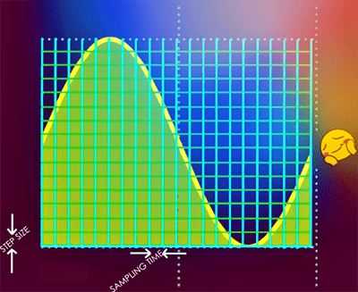
- The ADC port takes samples from the analog input signal at specific time intervals. These intervals are called sampling time. For every sample, the signal level is compared to a level called a step size. A number equal to the steps multiplied by the step size represents the analog signal on the given interval.
- The step size is dependent on the resolution which is often measured in bits. Since the Arduino has a 10-bit ADC by default, there’re 210 possible steps by which the analog signal can be represented.
Oh, talked enough! More about continuing playing with the ADC electronics in-depth will be explained in a different post. Now let’s go back to the read and display experiment.
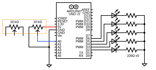
So, the first step is to rig up the hardware setup. As you can see below, the structure is relatively simple. Only a few simple components – that’s it. The analog sensor is nothing else but a ready-to-hand slide potentiometer (if you think ahead, you can play with almost anything analog).
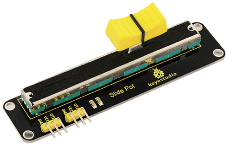
A slide potentiometer (slide pot) presents an interesting user interface that can be more intuitive than a traditional rotating potentiometer and can be quite useful in many applications.
Below is the image of a quite common dual slide potentiometer module. Note that there’re two 3-pin male header connectors on the board, one for each pot:
- GND: 0V (Ground)
- VCC: V+ (3.3V/5V)
- OTA/OTB: OUT (Wiper Output)
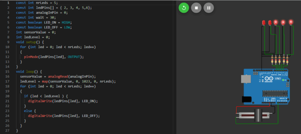
Here’s a sample sketch for this Arduino Uno experiment (tweak it to suit your needs):
const int nrLeds = 5;
const int ledPins[] = {2, 3, 4, 5, 6};
const int analogInPin = 0;
const int wait = 30;
const boolean LED_ON = HIGH;
const boolean LED_OFF = LOW;
int sensorValue = 0;
int ledLevel = 0;
void setup() {
  for (int led = 0; led < nrLeds; led++)
  {
    pinMode(ledPins[led], OUTPUT);
  }
}
void loop() {
  sensorValue = analogRead(analogInPin);
  ledLevel = map(sensorValue, 0, 1023, 0, nrLeds);
  for (int led = 0; led < nrLeds; led++)
  {
    if (led < ledLevel ) {
      digitalWrite(ledPins[led], LED_ON);
    }
    else {
      digitalWrite(ledPins[led], LED_OFF);
    }
  }
}
If everything is wired correctly and the sample code has been uploaded to the Arduino, the program starts to run and shows the slide pot values through the bar graph composed of five LEDs. Depending on your use case, you might have to implement some optimizations, if you require a perfectly linear distribution of the analog value range.
WokWi Simulation Link https://wokwi.com/arduino/projects/314129242028769856
Coffee Break!
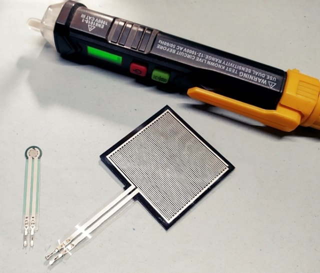
Well, you’re all caught up! Next, we will use the knowledge we gathered so far and use it to extend our experiment to work with a force-sensitive resistor (FSR). An FSR is comprised of a conductive polymer material pressed between two electrode layers, giving it the ability to electrically respond to changes in stress and strain.

So, an upcoming tutorial explores force-sensing resistors with microcontrollers and how to test and calibrate them. Let’s see how it goes!