As a beginner, Arduino microcontroller is probably your best bet. So, this time get ready to learn how to build Arduino based infrared (IR) remote control projects at ease!
Assume that you’re in the process of making some devices yourself, and planning to control them remotely using a common infrared remote-control handset you might have lying around. That’s great! In order to do that, the first step is to be able to decode the invisible infrared messages transmitted by that infrared remote-control handset. In this post, I’ll try to explain how to proceed to analyse different key button codes and discover how to employ them in do it yourself electronics projects.
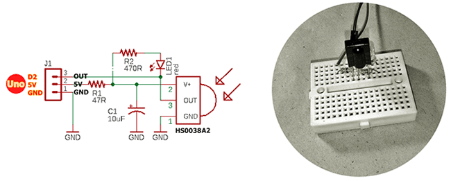
You can start by identifying the signals transmitted by your infrared remote control. An easy hardware frontend that really makes decoding infrared signals easy for you is the HS0038A2, which’s a very common and cheap photo module designed for PCM remote control systems.
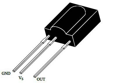
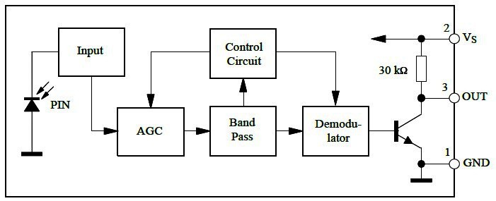
The HS0038A2 is a miniaturized 3-pin receiver for infrared remote-control systems supporting all major transmission codes. The PIN diode and preamplifier is assembled on the lead frame, and the epoxy package is designed as IR filter. The demodulated output signal can directly be decoded by a microprocessor.
Now prepare your simple hardware setup as depicted in the below circuit diagram. The LED1 in this circuit is an optional ‘status’ indicator. I have found this minimal setup has pretty good stability and range, and easily work across a room.
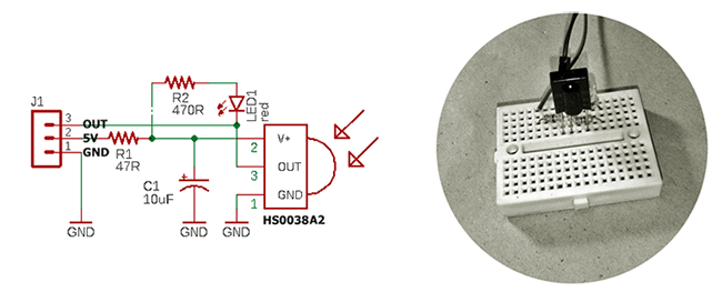
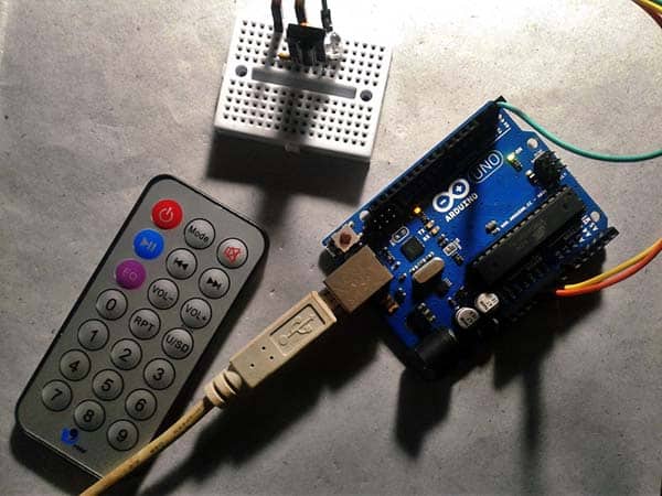
To test your quick build, simply point the remote control transmitter (handset) at the HS0038A2 receiver and press a button on the remote control. You can see LED1 starts winking in tune with the infrared pulse train beaming on the sensor face.
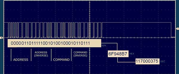
An infrared remote control works by turning an infrared LED on and off in a particular pattern at a modulation frequency, typically 36-38kHz. Each key button on the remote control handset has a particular code (typically 12-32 bits) associated with it and broadcasts that code when the key button is pressed down.
The easiest way to decode the infrared signals is to use your HS0038A2 setup with an Arduino Uno microcontroller. Various libraries are available online to help you decode and record the codes from your existing remote-control transmitters. One best library I’ve found a while before is the “IRLib2”. Another famous one for Arduino is Ken Shirriff’s multi-protocol infrared remote library “IRremote”( https://github.com/shirriff/Arduino-IRremote). As rightly told by someone, a good code library isolates the application programmer from the hardware details and the inner workings of devices and provide him/her with an API that makes it easy to use the hardware without knowing or caring what’s going on behind the scenes.
Related primer https://www.electroschematics.com/ir-decoder-encoder-part-1/
So, here’s the updated hardware wiring pointer. It’s pretty simple, you only need to connect your HS0038A2 setup to D2-5V-GND headers of Arduino Uno
… And upload this code:
#include "IRLibAll.h"
/* https://github.com/cyborg5/IRLib2 */

IRrecvPCI myReceiver(2); // HS0038A2 O/P to ARDUINO UNO D2

IRdecode myDecoder;

void setup() {
  Serial.begin(9600);
  myReceiver.enableIRIn();
  Serial.println(F("Ready! Waiting for IR Signals..."));
}

void loop() {

  if (myReceiver.getResults()) {
    myDecoder.decode();
    myDecoder.dumpResults(true);
    myReceiver.enableIRIn();
  }
}
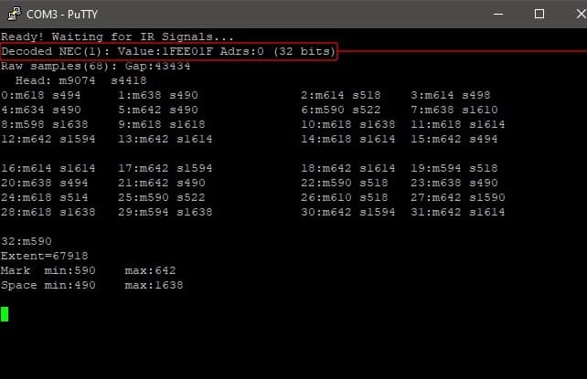
After the setup has completed, open the Arduino Serial Monitor and ensure that it’s set to 9600 baud. And then aim your infrared remote control at the HS0038A2 receiver and press a button. In this example I pressed the “Power” and “Mute” buttons on my randomly picked test handset. See the outcomes below.
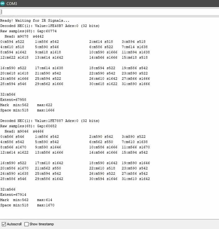
Let’s look at what’s significant here. The most important part is the first line which tells us that the protocol detected was “NEC” which is protocol number “1” in the library supported protocols. The PWR button data received was the 32-bit hexadecimal value 1FE48B7. This 32-bit number uniquely identifies the button that I pushed. The MUTE button on the handset returned the value 1FE7887. The rest of the information is the raw timing data of the actual marks (on time) and spaces (off time) received, and is useful in trying to understand and supported infrared remote-control protocols.
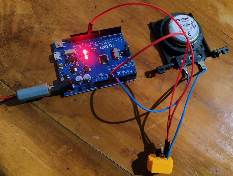
You can of course fiddle with various remote controls lying around to ‘record’ the button codes, and then use them in your projects. For example, I used the aforesaid data values in an example code to turn on a single NeoPixel (WS2812B) Module in blue with power button, and in pink with mute button. It’s very crude, I know, but hopefully a good starting point for you.
This the hardware setup for that funny project:
![]()
And, this is the Arduino Sketch:
#include <Adafruit_NeoPixel.h>
#include <IRLibAll.h>

/* https://github.com/adafruit/Adafruit_NeoPixel */

IRrecv myReceiver(2); // HS0038A2 IRRX O/P = D2
IRdecode myDecoder;


Adafruit_NeoPixel strip = Adafruit_NeoPixel(1,6,NEO_GRB + NEO_KHZ800);
// WS2812B NeoPixel Din = D6

void setup() {
  strip.begin();
  strip.show();
  myReceiver.enableIRIn();
}

void loop() {
  if (myReceiver.getResults()) {
    myDecoder.decode();
    if (myDecoder.protocolNum == NEC) {
      switch(myDecoder.value) {
        case 0x1FE48B7:  //POWER BTN
          strip.setPixelColor(0,0,0,255); //Blue
          break;

        case 0x1FE7887:  //MUTE BTN
          strip.setPixelColor(0,255,0,255); //Pink
          break;
      }
    strip.show();
    myReceiver.enableIRIn();
    }
  }
}
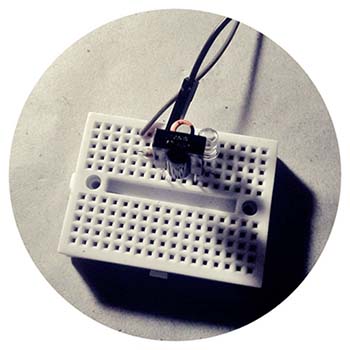
My quick test prep looked like this:
![]()
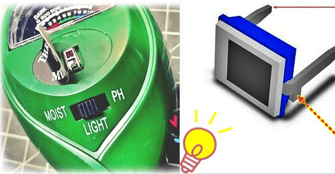
And, random shots of the test run (my cheapo camera utterly fails in capturing true colors):
![]()
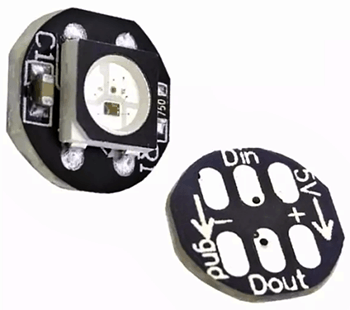
This is the photograph of a cheap WS2812B Module similar to the one used by me. Related project https://www.electroschematics.com/arduino-addressable-leds-splendid-projects/
Back again, I’m in the process of preparing the second part of this article. Until then, stay inspired. As usual, if you experience any difficulties while following the ideas shared here, please leave a comment below, and I’ll get back to you as soon as I can. Happy decoding and tinkering!