How to build a cheap and cheerful musical doorbell using a few electronics parts laying around? I recently planned to try one idea, and this week I had the time for that. Now, I would like to share 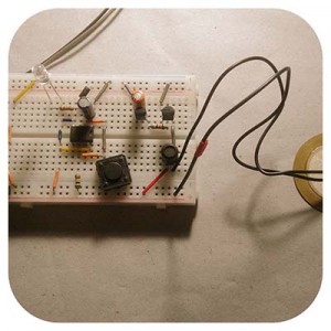 with you a quick overview of the little project. So, in this tutorial, you are going to learn how to make a simple musical doorbell in a very easy way which is also very low cost!
What can we get from old things? See, this project is based on a very old melody generator chip which perhaps gives you a nostalgic vibe! The circuit for the musical doorbell can be seen below and is relatively simple.
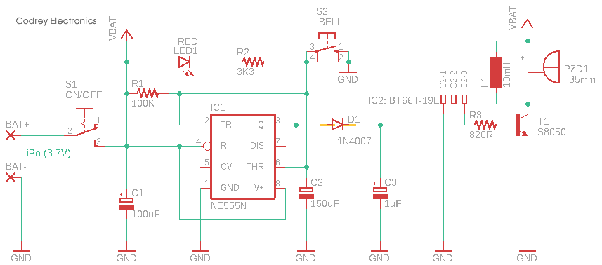
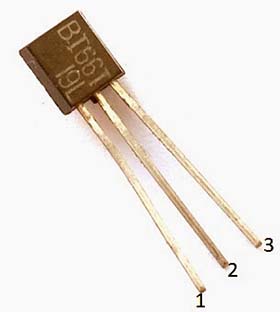
As pointed above, at the heart of the circuit is a very old melody generator chip – the BT66T (IC2). The BT66T is an easy to use little melody generator IC, mainly used in circuits where a melody has to be played as a notification for the user. The BT66 can work on low DC voltage (0.3V to 3.5V) and consumes very small current (1uA) during operation. Actually, BT66T is an equivalent of the UM66 melody generator IC. Complete technical details of the IC available in the TO-92 package can be found in the datasheet given at the end of this page.
BT66T Pin Configuration
- Pin 1 = Gnd (Vss/0V)
- Pin 2 = Positive (Vdd/3.3V max)
- Pin 3 = Output (BD)
It’s worthy to note that the BT66T comes in five different part numbers. Each part number has the capability to play a unique tone. The part number and its respective tone is mentioned below, you can Google the tone name to listen to the type of tone the IC will play.
- BT66T-19L = For Elise
- BT66T-02L = Jingle Bell
- BT66T-08L = Happy Birthday
- BT66T-12L = Love Story
- BT66T-68L = It’s a Small World
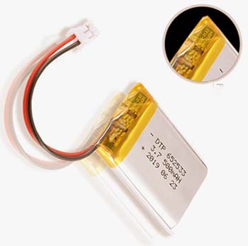
The musical doorbell circuit presented here is configured to run on a small single-cell (1S) lithium-polymer (LiPo) battery (3.7V/600mAh). The ubiquitous NE555N chip (IC1) is included deliberately in this design to keep the BT66T chip alive for a finite time (Near 15s) on every doorbell button (S1) trigger. Note that the red light (LED1) is just a ‘marker’ for the doorbell switch – remember to mount it very close to the pushbutton switch (S1).
The output circuit is a simple common emitter driving the piezoceramic disc. The BT66T can drive a piezoceramic disc directly, but that’s not enough to get a reasonable outcome. So, one S8050 transistor (T1) is used to drive the 35mm piezo ceramic disc (PZD1). The 10mH inductor (L1) wired across the piezo disc is used to make the tone output loud enough for a rather quiet home.
The S8050 transistor can also be used to drive a larger loudspeaker if you need more volume, but I would not use one less than 16Ω/1W. If you use a powerful loudspeaker, you may want to decrease the value of R3 (to 220Ω) or eliminate it completely by replacing it with a jumper.
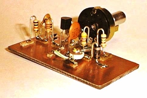
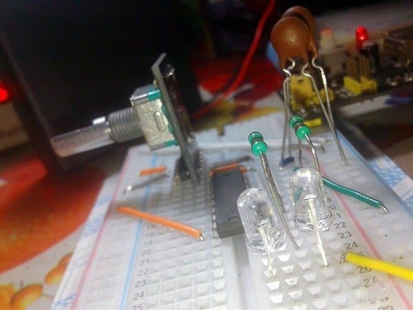
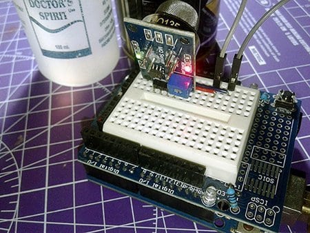
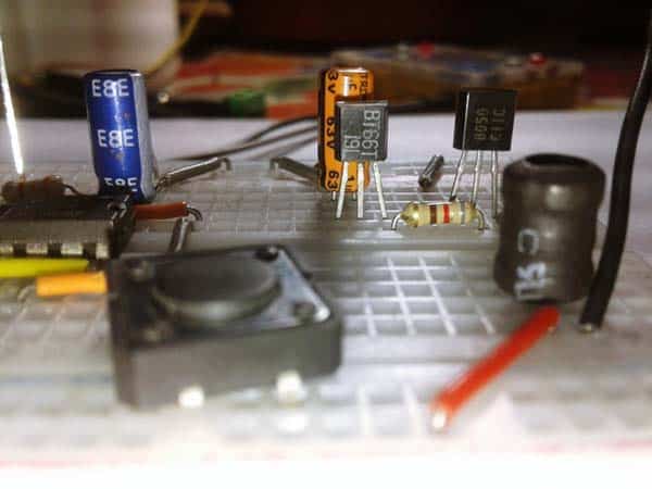
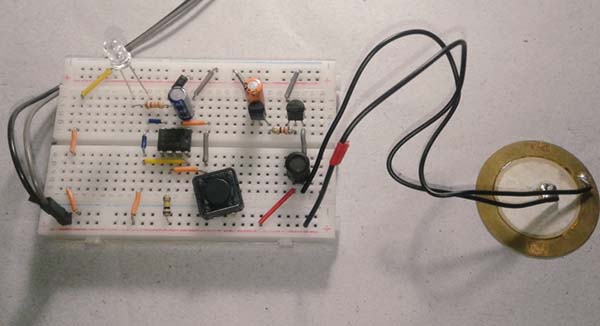
Below you can see casual snaps of my quick breadboard prototype, powered by the 1S LiPo battery (sadly it eluded the camera).
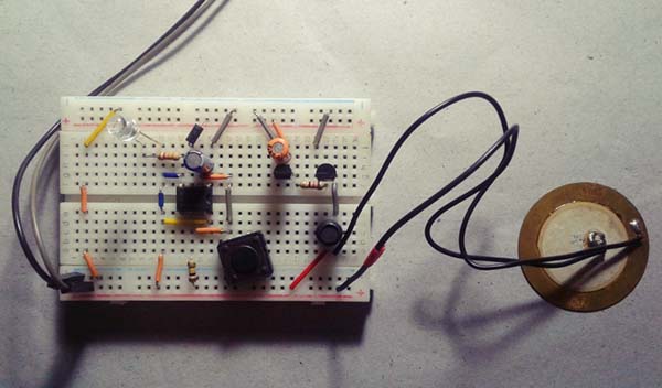
Since all the parts are thru-hole with no SMDs (surface-mount devices), a small piece of perfboard is enough for the construction of the entire circuitry. And, you can use an ordinary soapbox as the doorbell enclosure. Well, if you have an artistic mind (and a bit of carpentry skill), then go for a homemade wooden doorbell enclosure. Here you can find a funny do it yourself guide http://www.zentastic.com/blog/2010/08/22/make-diy-wooden-doorbell-enclosure-and-more/
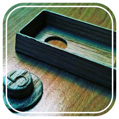
A few words on the design of the piezo resonating cavity: Naturally, the piezoelectric diaphragm/piezo ceramic disc alone does not produce a high sound pressure level (SPL). This is because the acoustical impedance of the element does not match that of any open-air loading. Therefore, it is necessary to mount the element in a resonant cavity designed to enhance the SPL for a specific frequency. Remember, the resonating cavity must be made to match the acoustical impedance of the element and the encased air – this is a viable reference guide for you https://www.aurelienr.com/electronique/piezo/applic.pdf
A side note: Sound is simply a wave of varying air pressure. These pressure waves cause a thin membrane in the ear to vibrate and the brain interprets these vibrations as sound. A decibel (dB) scale is used to describe the sound pressure level or loudness of a sound (An increase of 20 dB means that the SPL increased by ten times)!
In the end, you need to add a crude USB-LiPo charger circuit to the main musical doorbell circuitry. Look below to get it.
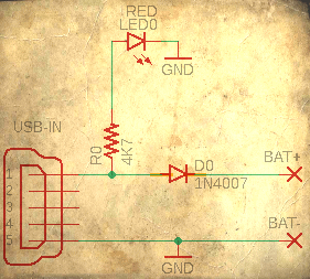
The above addition lets you recharge the internal LiPo battery pack of your musical doorbell through an external USB travel charger or USB power bank at ease. As you can see this is a forged idea but it will work safely here as the LiPo battery employed in this design has a reliable inbuilt protection mechanism (see below). Also read https://core-electronics.com.au/tutorials/our-guide-for-using-lipo-batteries.html
Moving forward, recently I successfully completed a couple of experiments with a bunch of ridiculously cheap Chinese musical COB modules bought in last year (and now looking for something different). So, if you are still interested, stay tuned for my succeeding post in this series. Let us take a look at a bit more modern version!
- BT66T Datasheet https://datasheetspdf.com/pdf-file/517048/Formox/BT66T/1
- NE555 Datasheet https://datasheet.octopart.com/NE555N-STMicroelectronics-datasheet-7269381.pdf
- S8050 Datasheet http://www.unisonic.com.tw/datasheet/S8050.pdf