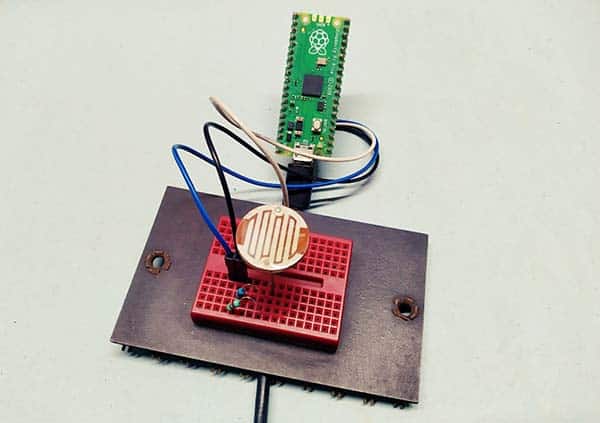
In this tutorial, we will learn how to interface a big photoresistor with Raspberry Pi Pico. Since the Raspberry Pi Pico microcontroller provides analog ports, we can easily do a number of projects using common analog sensors. A useful case is with photoresistors.
A photoresistor is in fact a light-dependent resistor (LDR). As the name suggests, it acts just like a variable resistor, changing its resistance in response to how much light is falling on it. Usually, a photoresistor has a very high resistance in the absence of light and very low resistance when stepped into the light.
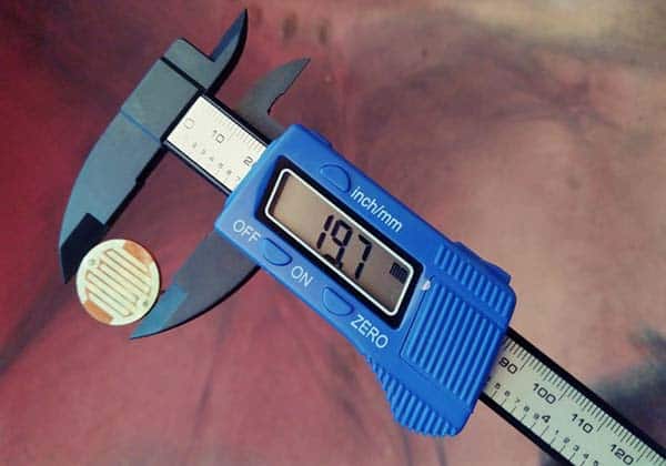
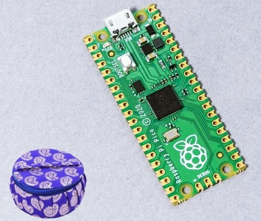
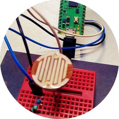
The most common photoresistor commonly used in similar projects is the 5mm LDR (GL5528), but this time our choice is a completely different one. That is, a large 20mm LDR (GL20258).
Quick specifications of the GL20258 LDR are shown below.
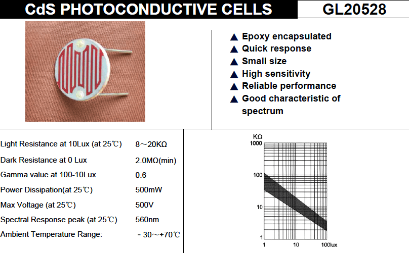
Referring above specs, note that the “Light Resistance” is determined after the photoresistor was irradiated by 400 to 600Lux light for 2 hours, and then test with 10Lux under a standard light source – illuminant A.
(Wikipedia says, CIE standard illuminant A is intended to represent typical, domestic, tungsten-filament lighting. Its relative spectral power distribution is that of a Planckian radiator at a temperature of approximately 2856K. CIE standard illuminant A should be used in all applications of colorimetry involving the use of incandescent lighting unless there’re specific reasons for using a different illuminant).
And, the “Gamma Value” is the logarithm of the ratio of the standard resistance value under 10Lux and that under 100Lux.
Γ =Lg(R10/R100) / Lg(100/10)
(R10 and R100 are the resistances under 10Lux and 100Lux respectively).
Call to mind, Raspberry Pi Pico is the Raspberry Foundation’s first entry into the domain of Arduino-style microcontrollers. The Raspberry Pi Pico board is centered on Raspberry’s own SoC (System on a Chip) – the RP2040 which holds a dual-core ARM Cortex-M0+ CPU along with memory and a collection of I/O circuitry. Raspberry endorses programming the Pico board in either C/C++ or MicroPython.
The LDR should be used with a resistor to form a potential divider for proper circuit operation. Below you can see a configuration where the voltage output (Vout) increases as light increases.
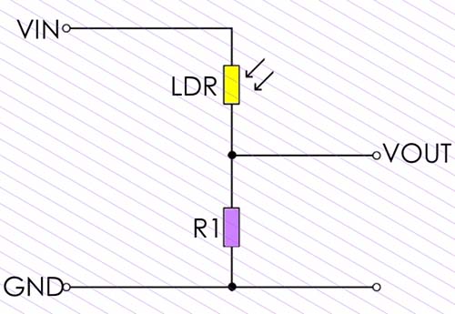
The potential divider formula applicable here is: VOUT = R1/LDR+R1 x VIN.
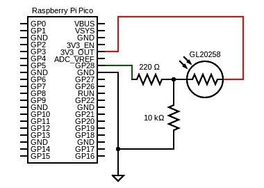
So, if you feed this VOUT to an ADC pin of Raspberry Pi Pico (GP28/ADC2 in this experiment), compared to the reference voltage (3.3V) provided by Raspberry Pi Pico, you will get a value proportional to the light exposed to the photoresistor. With ADC module from MicroPython, this value will range between 0 and 65535, and we’ll transform it roughly into a percentage scale (0% and 100%).
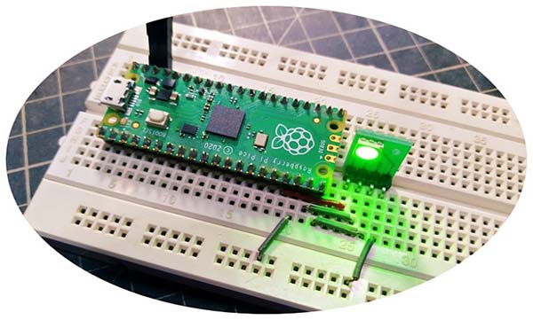
Below you’ll find the proposed wiring diagram.
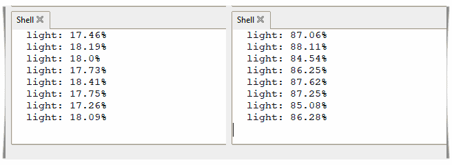
Now run this simple code snippet in your Thonny IDE and you will start seeing your readings printed on Thonny Shell, as in the succeeding screenshot taken while the photoresistor sees nearby light at random levels (source of inspiration https://peppe8o.com/).
from machine import ADC, Pin
from time import sleep

photoPIN = 28

def readLight(photoGP):
    photoRes = ADC(Pin(28))
    light = photoRes.read_u16()
    light = round(light/65535*100,2)
    return light

while True:
    print("light: " + str(readLight(photoPIN)) +"%")
    sleep(1)
Note that each photoresistor will act a little differently than the other, even if they are from the same batch. For this reason, a photoresistor shouldn’t be used to try to measure precise light levels in lux or millicandela. Instead, you can expect to only be able to detect basic light changes.
This table indicates the approximate resistance of the GL20258 photoresistor used in my experiments at different light levels:
| LIGHT LEVEL (lux) | PHOTORESISTOR VALUE (Ω) |
|---|---|
| 0 (darkness) | >1M |
| 10 (dim room light) | 12K |
| 300 (bright room light) | 2K |
| 1K (daylight) | 1K |
| 20K (too close to a fluorescent lamp) | <100 |
And that’s all. I hope you like this simple tutorial interfacing a bombastic photoresistor with Raspberry Pi Pico. As always, you can post comments down below. Moreover, if you have any pragmatic suggestions, feel free to share!