In this article, I’ll dig into everything you need to know when it comes to the build of your own minuscule wired/wireless spy camera system. Since the spy camera itself is one of the most important elements of a spy camera system, let me start this first part with some useful pointers on how to choose the right camera and how to use it in your spy/security camera project.
STEP 1 – Buy one cheap FPV Camera
Most people believe that FPV cameras are only used in RC drones, but they’ve a myriad of uses for projects of all kinds. Note that “FPV” camera means “First Person View” camera or simply the onboard flight camera! https://www.dronezon.com/learn-about-drones-quadcopters/what-is-fpv-camera-fov-tvl-cmos-ccd-technology-in-drones/
There are literally thousands of FPV cameras available on the market today, so I quickly picked a cheap one ($10) from Banggood.
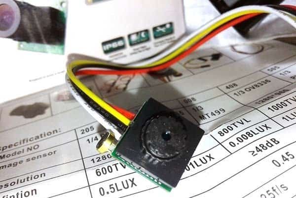
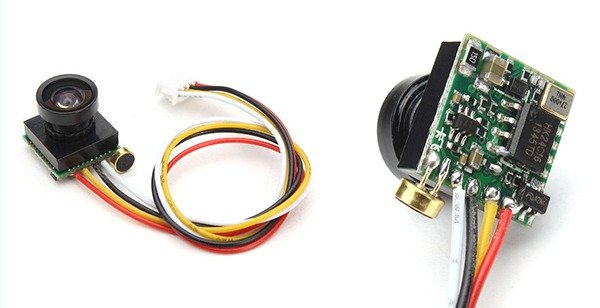
Banggood’s description for the camera is “Mini CMOS FPV 65 Degree 600TVL Camera 3.6mm NTSC/PAL For RC Drone”, and I bought its PAL version (Don’t buy the NTSC version for this project). Following is the camera’s key technical features and specifications provided by the seller.
- Lens: 3.6MM GLSAAES LENS, M12 screw thread, Visual Angle 65 degrees
- CMOS Sensor : HD Color CMOS
- Video Format : PAL/NTSC
- Pixel : 768(H)×576(V)
- Image Area : 4.752mm x 3.552um
- Sharpness : 600TV Lines
- Minimal Illumination : 5 Lux
- Video Output : 0Vp-p/75 Ohm
- Power Consumption : 90mA ±10%
- SNR (Signal to Noise Ratio) : 38dB
- DR (Dynamic Range) : 70dB
- Shutter : (N)1/60-1/10000s, (P)1/50-1/10000s
- Working Voltage : DC3.3-5.0V
- Weight : 2gm
- Size : 13*13*14MM
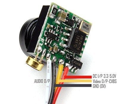
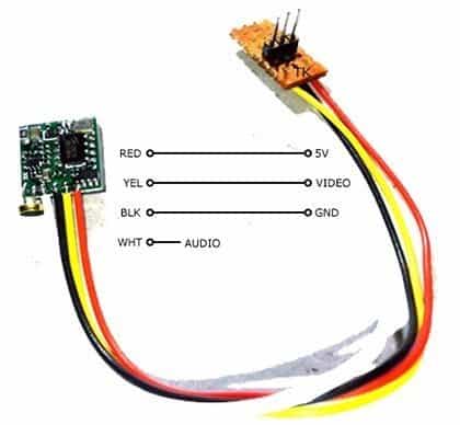
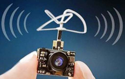
As can seen in the above image, my minuscule FPV camera comes with an integrated button microphone, too. The connection port has 4 colored wires – 2 wires (red and black) are for dc power supply input, 1 wire (yellow) is for composite video signal output, and the final wire (white) is for microphone signal (audio) output. The ground wire (black) is the ‘common’ lead for both the video and audio signal outputs (yellow & black = video, white & black = audio).
STEP 2 – Prepare your camera adapter circuit board
The camera module holds an onboard voltage regulator chip, so you can feed a dc voltage of 3.3V to 5V into it without any fear. Anyway since the camera electronics is very delicate, and my idea requires a 12VDC power supply, one power supply adapter circuitry is essential here. Keep note that, in this first version of the project (v1), the microphone feature is not exploited because of certain technical reasons.
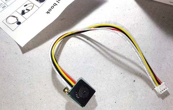
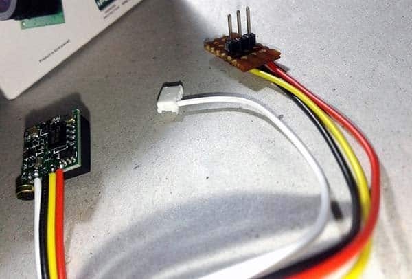
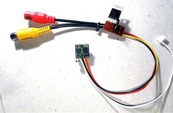
First of all, carefully detach the power supply and video wires (red-black-yellow) from the white 4-pin connector while keeping the microphone wire (white) intact. Next, take a bit of perfboard and solder those three wires to three male-header pins mounted on the perfboard.
And then prepare and attach a video output cable i.e. a 2-core cable with a molded female video output connector (a female RCA connector sometimes called cinch connector) at its end to the circuit board (https://en.wikipedia.org/wiki/RCA_connector).
Finally solder the 5V fixed voltage regulator, LM7805 IC (and its support components) in the adapter circuit board as shown in the next schematic, ofcourse with a female dc jack cable (https://potentiallabs.com/cart/buy-female-power-jack-with-cable).
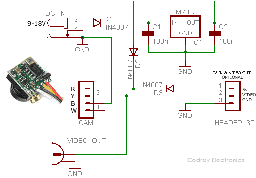
STEP 3 – Check out the assembly
Now you’ve a minuscule spy/security camera head which can be powered from any (~500mA) 9V-18V DC power supply (12V typical) source. For a quick test of the assembly, do connect the video output cable (yellow connector) to the video input socket of your color television, computer, or to the standard video input socket of any video signal monitor. Since the video output from this setup is a standard 1.0Vp-p/75Ω video signal, you don’t need any additional processing circuitry to run it. If things are okay, try to put the little build in a compact handmade or 3D-printed ‘black box’!
Nevertheless, if you’ve made it to this point, hurray, you merely completed the basic build of a wired spy/security camera system which comprised one FPV camera, a dc power supply, and a video monitor. The video cable, as the name suggests, carries the video signal to where it needs to go. Anyway, always try to keep the length of the video cable (in between the spy camera and the video monitor) as short as possible. Don’t extend it over 25 feet!
Now I’d like to turn your attention back to this good old simple video security camera project https://www.codrey.com/electronic-circuits/poor-mans-door-video-security-camera/
STEP 4 – Make it Wireless!
Here’s a shortcut to convert your wired spy/security camera you already built into a wireless one! If so you can easily use it as a surveillance camera in and around your home/office without using lengthy wires or cables. Let me show that inexpensive and easy trick!
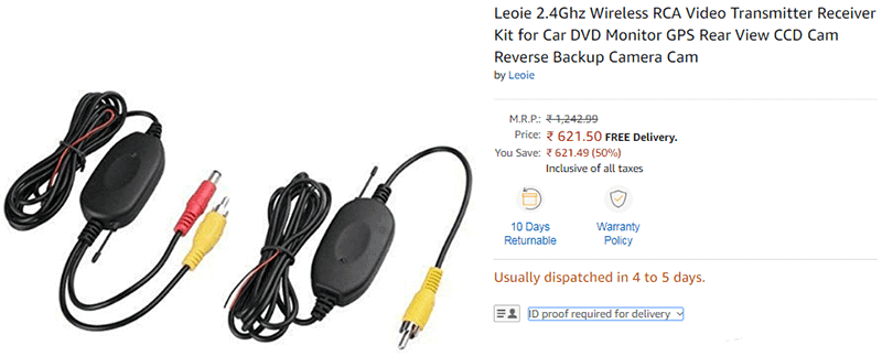
At first, buy a cheap 2.4GHz wireless RCA video transmitter and receiver kit from your favorite online seller (I bought one from Amazon India www.amazon.in/Leoie-Wireless-Transmitter-Receiver-Monitor/dp/B07X963QBN, and another one from Flipkart). Thereafter wire it up as marked in the next figure. Remember, a 12VDC power supply source is recommended here, but you can safely run the entire setup by a 9VDC power supply/rechargeable battery, too.
To make it easier and inexpensive, I’ve successfully tried some odd ideas, and it’ll be covered in the succeeding part of this article. Probably you can see the sequel in next month. Please stay tuned for that article!
I hope you enjoyed this primer. If you have any issues, please drop me a comment below and I’ll be happy to help!