Do you remember the feeling of building your own power electronics projects with a nifty analog chip? Something like DC-AC power inverter based on the SG3525?
The SG3525A is a pulse width modulator integrated circuit designed to offer improved performance and lowered external parts count when used in designing all types of switching power supplies. Why it’s time I fell love again with the nostalgic regulating pulse width modulating chip? Still, it’s available from many web-shops, and surprisingly it can be used as a poor man’s alternative to a tiny micro controller in a few fortunate situations!
Stand-alone PWM power driver presented here is, in fact, a high-current pulse width modulator designed around SG3525A/KA3525A to drive beefy brushed DC motors and/or powerful light emitting diodes. Duty cycle of the PWM of this basic design (shown next) can be adjusted from 0 to 100% (+/- 5%), and the frequency scale is in KHz. Operating voltage of the internal circuit is 9V DC by default but you can use DC supply inputs in other ranges without major alterations (refer official datasheet of the chip).
Using the nifty SG3525 chip as the key component offers more flexibility and reliability because it has the following features:
- 8 TO 35 V operation
- 5.1 V reference trimmed to ± 1 %
- 100 Hz to 500 KHz Oscillator range
- Separate oscillator sync terminal
- Adjustable dead time control
- Internal soft-start
- Pulse-by-Pulse shutdown
- Input Undervoltage lockout hysteresis
- Latching PWM to prevent multiple pulses
- Dual source/sink output drivers
Important pins of the chip (as used here) is:
| Pin No. | Pin Name |
|---|---|
| Pin1 | INV (-) input |
| Pin2 | N-INV (+) input |
| Pin5 | CT |
| Pin6 | RT |
| Pin9 | COMP |
| Pin12 | GND |
| Pin13 | VC |
| Pin15 | VCC |
| Pin16 | VREF |
And here, the oscillator frequency is: 1/CT(0.7xRT) ie. 1/ C1(0-7xR1+RP1). Tinkerers should note that recommended value for CT is from 1n to 100n, and RT is 2K-150K. 10K Trimpot RP2 is for duty cycle adjustment. In the design, driver outputs of the chip are grounded. The VC terminal is switched to ground by the internal totem-pole source transistors on alternate oscillator cycles.
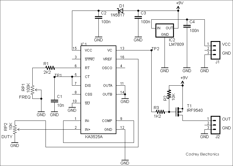
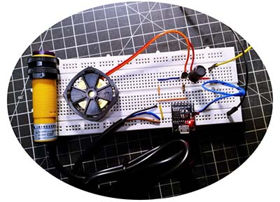
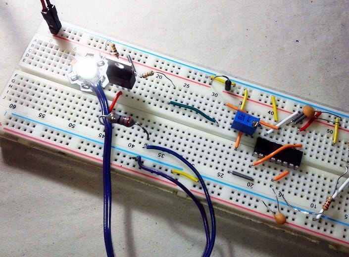
Author’s experimental setup on breadboard (see next figure) was tested with a 1W star white LED connected between OUT (+) and GND terminals of J2 through a 22 Ω /1w resistor. With an oscillator frequency near 20KHz, smooth brightness control of the LED was experienced by the 10K multi-turn trim pot RP2.
Further, the right logic action (high duty cycle = high brightness) was performed by the setup because of the P-channel Power Mosfet IRF9540 (T1). The driver section obviously needs some refinements, well, set off your homework!
The SG3525 is a full-featured, versatile monolithic integrated PWM chip suitable for a variety of switching power supply controller by using constant frequency pulse width modulation scheme. Since its internal integrates oscillator, PWM comparator, error amplifier, under voltage lockout circuit, soft start control circuit, and reference voltage generator, a thorough walk-through will give you more ideas to build your own power electronics projects. Further, you can interface a small microcontroller/logic chip with it to adjust/control the switching frequency and duty cycle.
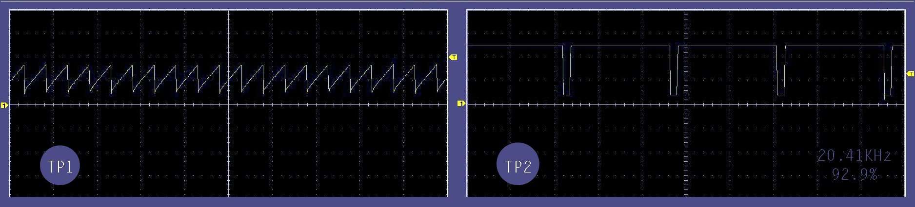
Shown next is the random oscillograms captured by my USB scope while I was experimenting with my breadboard prototype.